098-00720-000 Revision D1 – February, 2018 SyncServer 600 Series User’s Guide 55
Chapter 2 Installing
Signal Connections
1. Create a custom cable using the supplied Molex connector housing and
terminals. The terminals need to be crimped to the wires.
2. Connect the other end of the DC cable to nominal 24VDC or 48 VDC.
3. Repeat steps 1-2 for the second DC power connector.
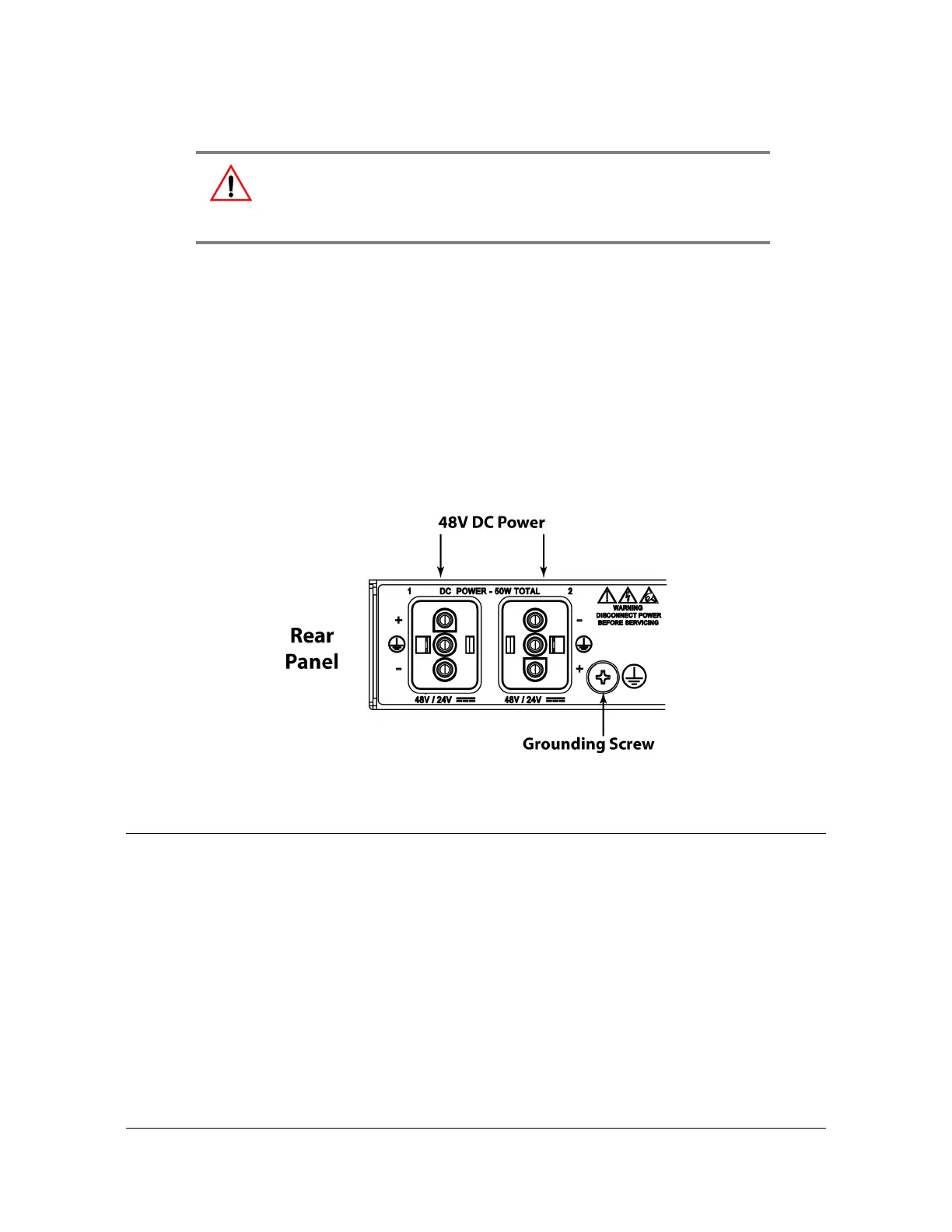
4. The positive wire must be connected to the positive terminal (+) and the negative
wire to the negative terminal (-). The ground connection should only be
connected to ground and not to a power supply.
Figure 2-9. SyncServer S6x0 Dual DC Power Connectors
Signal Connections
The connectors for the SyncServer S6x0 are located on the rear panel.
Communications Connections
The communication connections allow user control of the SyncServer S6x0. The
EIA-232 serial port and Ethernet port 1 (LAN1) are located on the rear panel are
shown in Figure 1-9.
Warning: To avoid possible damage to equipment, you must provide
power source protective fusing as part of the installation. The
SyncServer S6x0 is intended for installation in a restricted-access
location.