56 SyncServer 600 Series User’s Guide 098-00720-000 Revision D1 – February, 2018
Chapter 2 Installing
Signal Connections
Ethernet Port 1
Ethernet port 1 is a standard 100/1000 Base-T shielded RJ-45 receptacle on the
rear panel of the unit. It is used to provide connectivity to a web interface and to an
Ethernet local area network (as well as for NTP input/output). To connect the
SyncServer S6x0 to an Ethernet network, use an Ethernet RJ-45 cable. See Table
2-2 for connector pinouts.
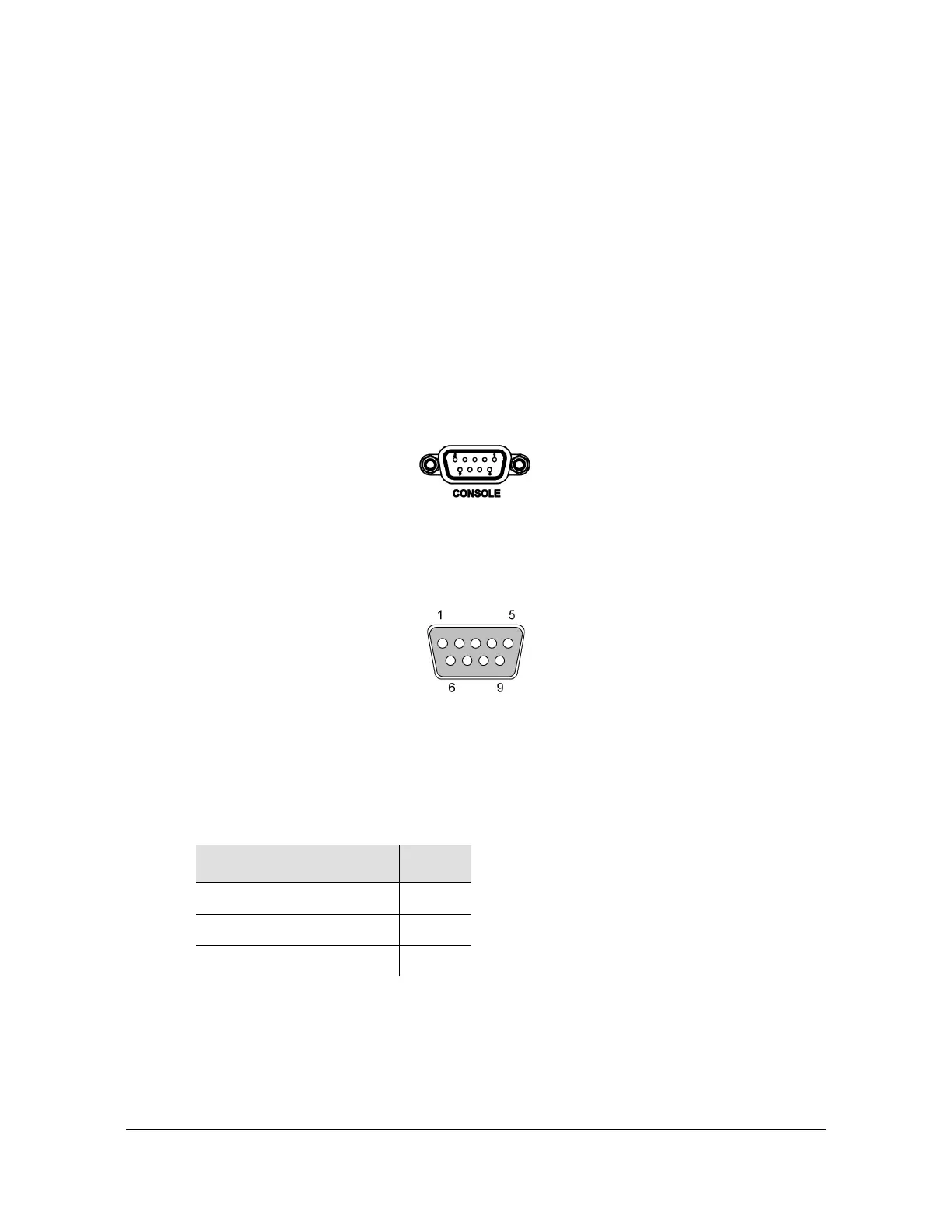
Serial (Console) Port
The serial port connection is made through a DB-9 female connector on the rear
panel of the unit. This port, which supports a baud rate of 115.2k (115200-8-1-N-1),
allows you to connect to a terminal or computer using a terminal emulation software
package for remote monitoring and control. This port is also used for serial data
(NENA ASCII time code, Response mode). When connecting to this port, use a
shielded serial direct connect cable.
Figure 2-10. Serial Port Male Mating Connector Pins
Figure 2-11 shows the DB-9 male connector that mates with the serial port on the
SyncServer S6x0.
Figure 2-11. Serial Port Male Mating Connector Pins
Table 2-1 describes the DB-9 connector pin assignments for the serial port
.
Table 2-1. Serial Port Connector Pin Assignments
Signal Pin
TXD 2
RXD 3
Ground 5