App - 7
17
MAINTENANCE AND
INSPECTION
18
ERROR MESSAGE
AND SYSTEM
ALARM
APPENDICES
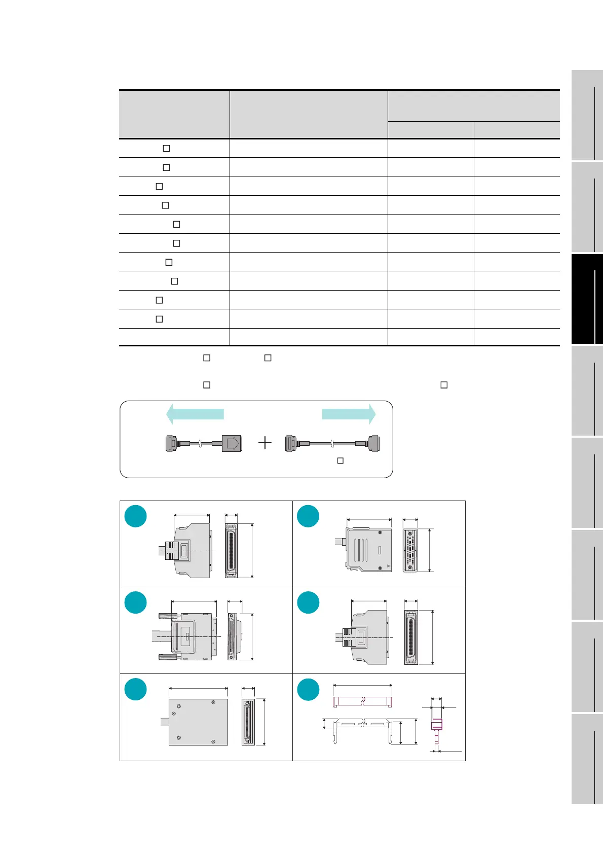
Appendix 1 External Dimensions
BUS connection cable specifications
*1: The GT15-C EXSS/GT15-C BS cable has a grounding wire (1 m).
Be sure to connect the wire to control panels.
*2: The GT15-C EXSS-1 is the set product consisting of (GT15-EXCNB+GT15-C BS). (Refer to Fig. A)
Cable model Cable length (m(ft.))
Dimensions (mm) and
shape of the connector
GOT side PLC side
GT15-QC B
0.6(2),1.2(3.9),3(10),5(20),10(33) Fig. 3 Fig. 3
GT15-QC BS
15(49),20(66),25(82),30(98),35(120) Fig. 3 Fig. 3
GT15-C NB
1.2(3.9),3(10),5(20) Fig. 1 Fig. 2
GT15-AC B
0.6(2),1.2(3.9),3(10),5(20) Fig. 2 Fig. 2
GT15-A1SC B
0.7(2),1.2(3.9),3(10)5(20) Fig. 1 Fig. 1
GT15-A1SC NB
0.45(1.5),1.2(3.9),3(10),5(20) Fig. 4 Fig. 2
GT15-J2C B
1(3) Fig. 1 Fig. 6
GT15-370C B-S1
1.2(3.9),2.5(8.2) Fig. 4 Fig. 4
GT15-C EXSS-1
10.6(34.8),20.6(67.6),30.6(100) Fig. 4 Fig. 4
GT15-C BS
10(33),20(66),30(98) Fig. 4 Fig. 4
GT15-EXCNB 0.5(2) Fig. 5 Fig. 4
33.0 (1.30)
11.5
(0.45)
49.7 (1.96)
20.0
(0.79)
58.0 (2.28)
60.0 (2.36)
10.0
(0.39)
42.0 (1.65)
35.0 (1.38)
33.0 (1.30)
12.4
(0.49)
49.9 (1.97)
75.0 (2.95)
20.5
(0.81)
60.0 (2.36)
Fig.1
Fig.3
Fig.5
Fig.2
Fig.4
Fig.6
55.3 (2.18)
6.0
(0.24)
5.0
(0.2)
2.2 (0.1)
Unit : mm (inch)
5.8
12.9
(0.51)
(0.58)
14.8
Fig.A
PLC side GOT side
Fig.4 Fig.4 Fig.4Fig.5
(GT15-EXCNB)
buffer circuit cable
(GT15-C BS)
extension cable

 Loading...

