© 2014 Mold-Masters (2007) Limited. All Rights Reserved.
Revised 1 Oct, 2014
E-14
SEQUENCE VALVE GATE
External Wiring Connections
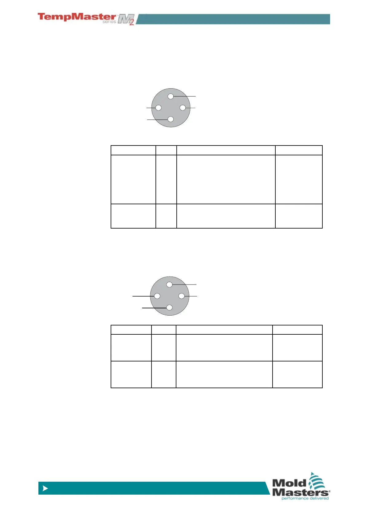
Inputs (North American Version)
Connector 1
Circuit Pins Description Format
Screw
Position
3 & 4 Accepts a Voltage source input
that relates to the main screw
position.
A calibration routine within the
controller adjusts actual input to
actual screw position.
0 to 10 Volts
Start Trigger 1 & 2 Sees a closed condition as a
signal to start the timer on the
valve sequence
Normally open
pair
Connector 2
Circuit Pins Description Format
Input A 1 & 2 Accepts a closing signal that can
be used as a Trigger for one or
more gates
Normally open
pair
(dry contact)
Input B 3 & 4 Accepts a closing signal that can
be used as a Trigger for one or
more gates
Normally open
pair
(dry contact)
4
1
23
4
Input B
(dry contact
pulse signal)
AMP04 Connector Number 2
Input A
(dry contact
pulse signal)
Handshake Inputs (Optional)
The SVG Controller has the ability to use handshake or feedback in-
puts from sensors in the actuator that tell whether the valve is “Open”
or “Closed”. There is no standard for this optional feature however
the SVG cabinet has space for a HAN24B-sized connector so a high
density connector such as the HAN72D would be tted on request in
order to accept feedback signals.
4
1
23
4
Start Trigger
Input
(Dry Contact)
Screw Position (-)
Screw Position (+)