B
Overview • Physical Overview
APEX1000 All-Purpose Edge QAM Software Version 2.4.x • Installation and Operation Manual
8
573408-001-a
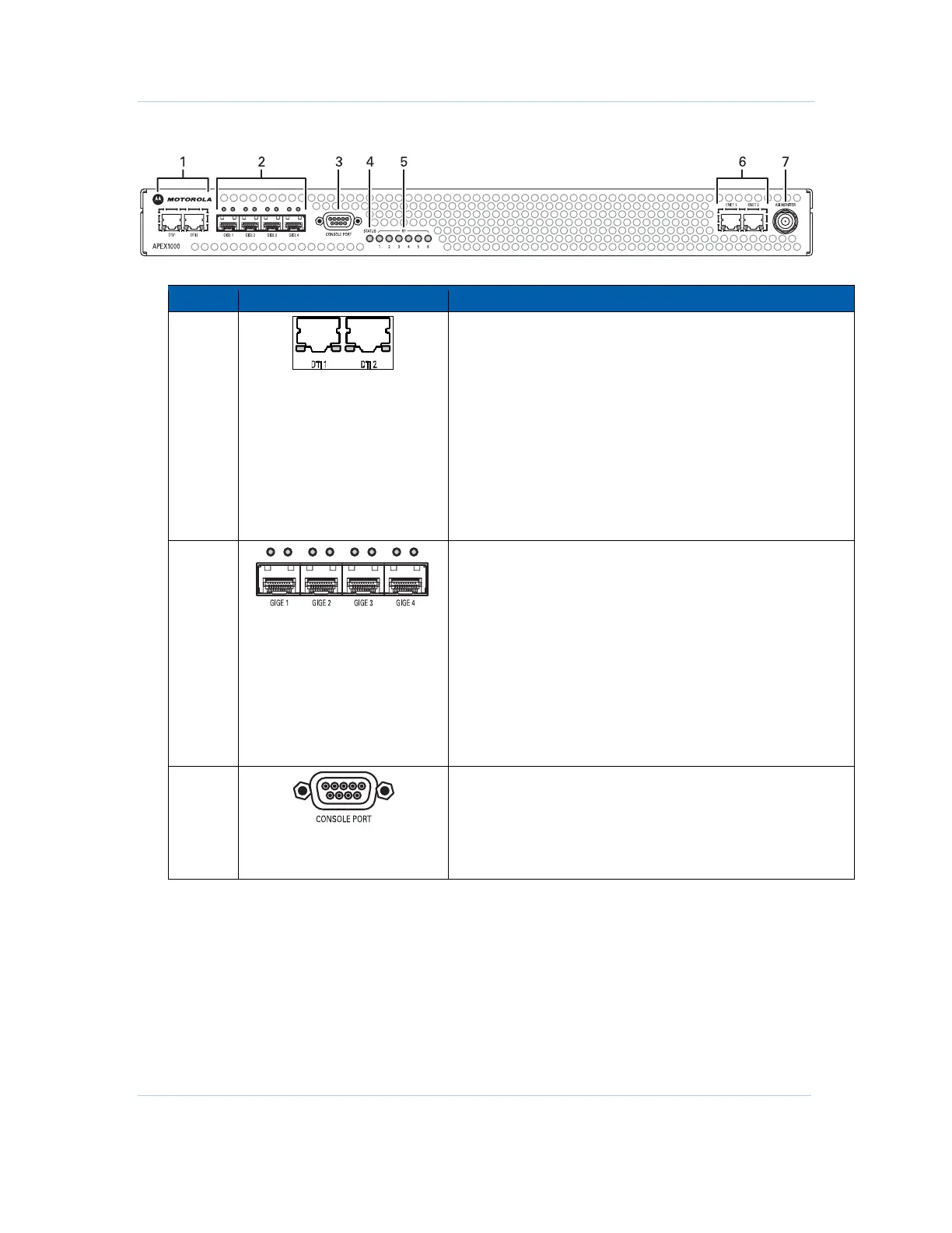
Front Panel Indicators and Connectors
Key Connector/Indicator Description
1
DTI (DOCSIS Timing Interface) Ports 1 & 2
These inputs (RJ-45 female connectors) provide redundant
connections to the DTI servers.
Located inside each input, each LED illuminates to indicate
status as follows:
• Off – Warm-up, free-run, holdover, or unit off
• Yellow – Fast
• Green – Normal or bridging
Note: Version 2.4.x of the APEX1000 supports DEPI in MPT
mode only. Support for PSP mode will be offered in a future
release.
2
GigE Inputs 1 through 4
GigE indicators – Located above each input, each LED
illuminates to indicate Ethernet link, data, and optics status as
follows:
• Off – No link or link down (the auto-negotiation failed, no
communication to partner, or no link pulse observed)
• Solid Green – Link up (auto-negotiation link pulse activity,
partners agree on capabilities, but no data traffic)
• Blinking Green – Link up and traffic (both transmit and
receive)
• Solid Red – Faulty or failed optical interface (can also indicate
that a GigE port is enabled, but no SFP modules are installed)
3
Nine-pin Console Port
• Top row connector pins are: 5, 4, 3, 2, 1
• Bottom row connector pins are: 9, 8, 7, 6
See
RS-232 Test Console Port for further information on menu
item selections.
 Loading...