B
Overview • Physical Overview
APEX1000 All-Purpose Edge QAM Software Version 2.4.x • Installation and Operation Manual
10
573408-001-a
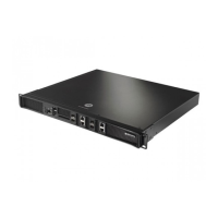
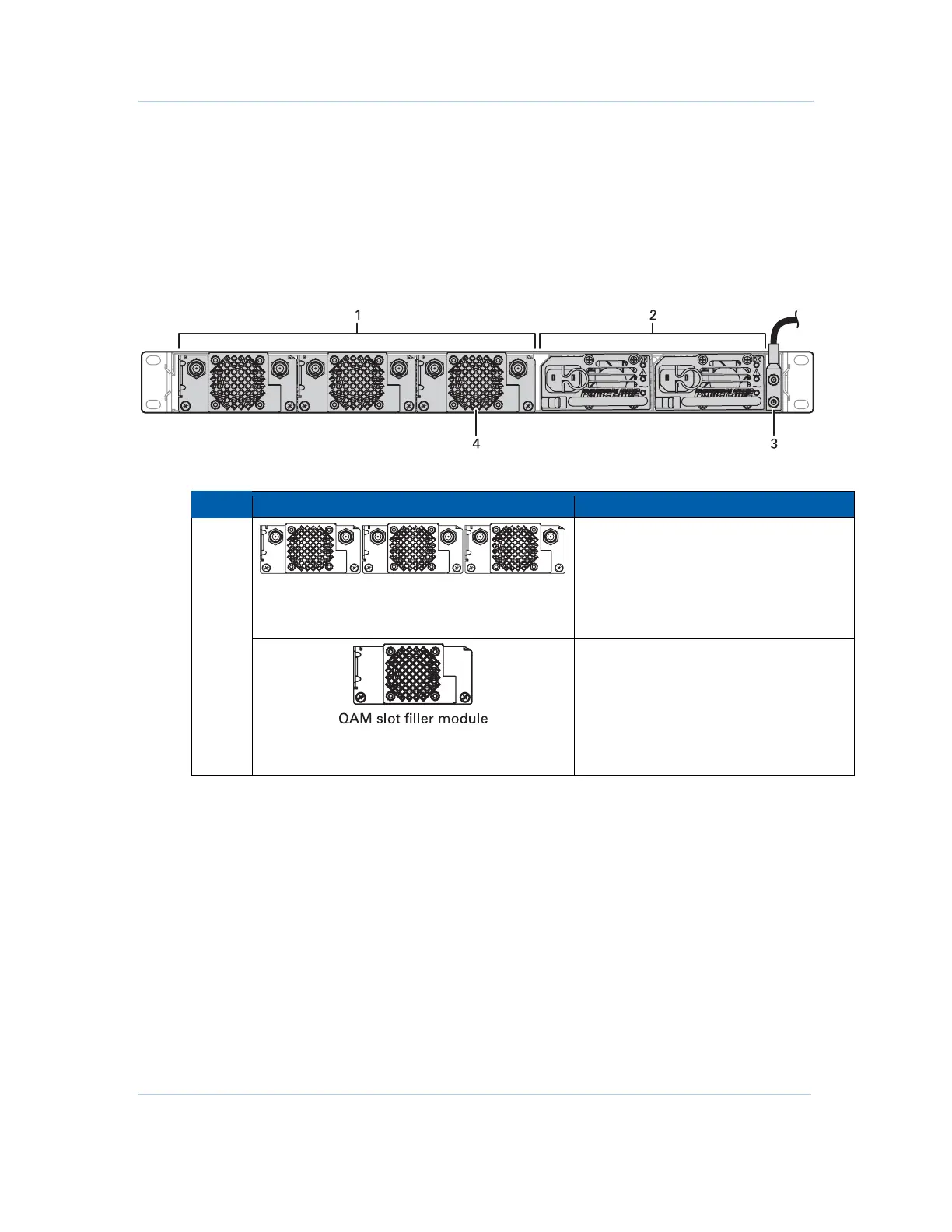
APEX1000 Rear Panel
The rear panel of the APEX1000 provides access to up to three replaceable QAM
modules with two RF connectors each. The replaceable power supply modules and
ground stud are also located on the back of the unit.
The following figure illustrates the APEX1000’s rear panel, shown with (optional)
redundant AC power supplies:
Figure 2-2 — APEX1000 rear panel
APEX1000 rear panel connectors
Key Connector/Indicator Description
Replaceable, hot-swappable QAM modules
(maximum three units). Each has QAM/UC
“F” type output connectors RF #1 & RF #2.
See
RFPM and Power Supply Modules for
additional details on identifying and
replacing a QAM module.
1
In APEX1000 units with less than the
maximum allowable three (3) QAM
modules, a corresponding number of filler
units must always be installed in the empty
slots.
Caution: For proper operation, all QAM
slots must be occupied at all times!
 Loading...