B
Installation • Installing or Removing GigE SFP Transceivers
APEX1000 All-Purpose Edge QAM Software Version 2.4.x • Installation and Operation Manual
35
573408-001-a
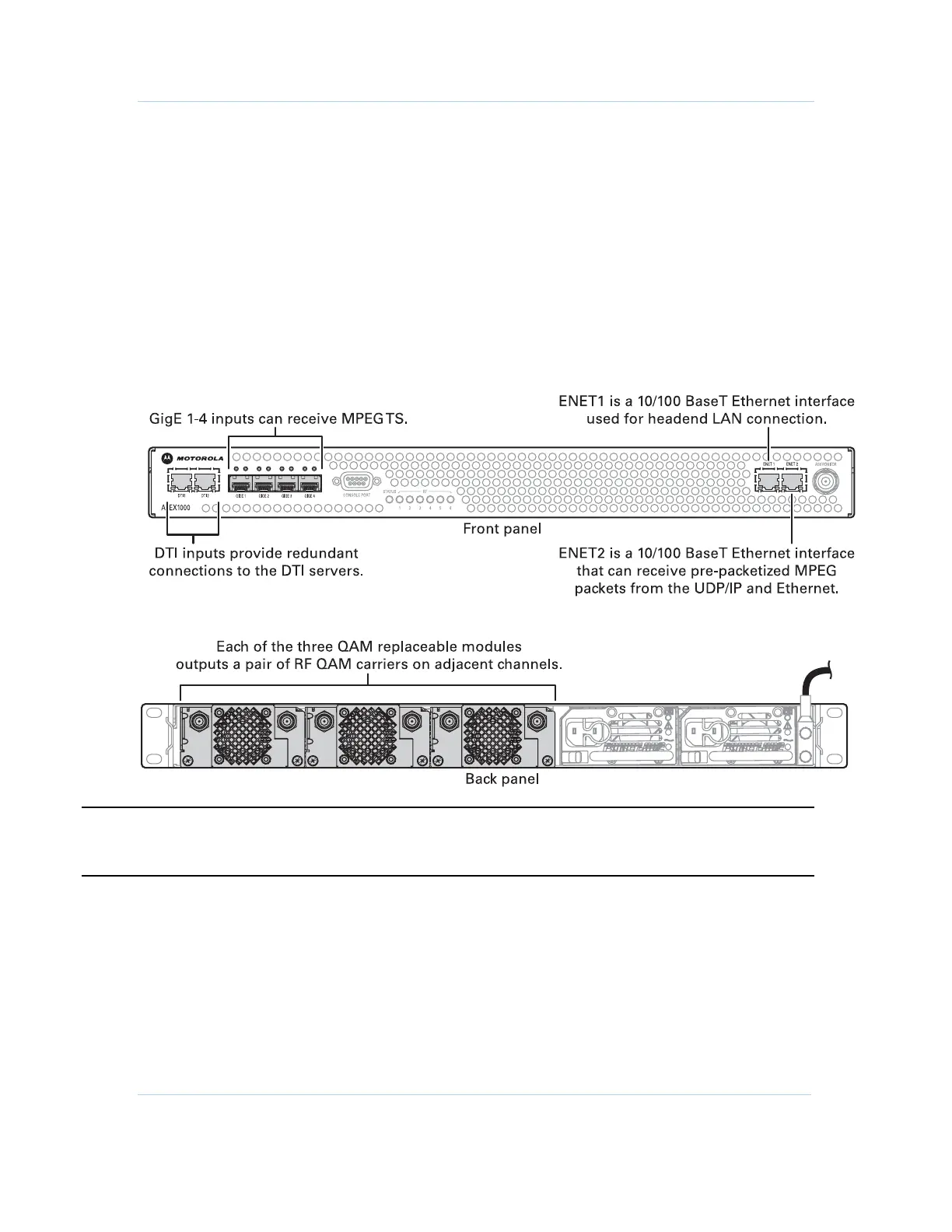
Connecting the Interface Cables
The Ethernet interface cable from ENET1 to the headend LAN is the only standard
cabling. All other interface cabling is contingent upon the APEX1000 configuration (as
defined by the specific system implementation).
Inserting or Removing Cables
Common F and BNC tools facilitate the insertion or removal of connectors from the
APEX1000. Typical tools are:
• The “F” connector removal tool from Toner (part number XQT)
• The BNC tool from Techni Tool (part number 702SC007)
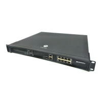
Figure 3-3 — APEX1000 front/rear panel I/O cable connectors
CAUTION To function properly, all RF Outputs must be terminated with 75 Ohms for the internal
RF Power Level detector. Unterminated RF Outputs may trigger an APEX RF Low Alarm.
 Loading...