B
Appendix E • RFPM and Power Supply Modules
APEX1000 All-Purpose Edge QAM Software Version 2.4.x • Installation and Operation Manual
304
573408-001-a
2. Position the module in the slot with the two captive screws located at the lower half
of the unit.
3. Carefully slide unit into the empty slot until flush with other units.
4. Tighten the two captive screws to secure the module to the chassis.
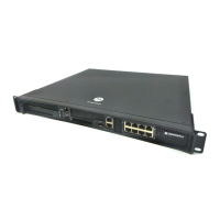
AC/DC Power Redundancy
The APEX1000 supports up to two dual hot-swappable redundant load sharing power
supplies (the system can operate with either one or two); supports two AC, two DC, or
one AC or one DC. In redundant mode, each power supply must be connected to an
independent power source that is attached to a dedicated circuit breaker. This circuit
breaker must comply with local building and electrical safety codes.
CAUTION Before removing and replacing a PS unit, certify that the APEX1000 is in full redundancy;
operating in non-redundant power will require a complete system shutdown while
removing and inserting a power supply module.
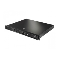
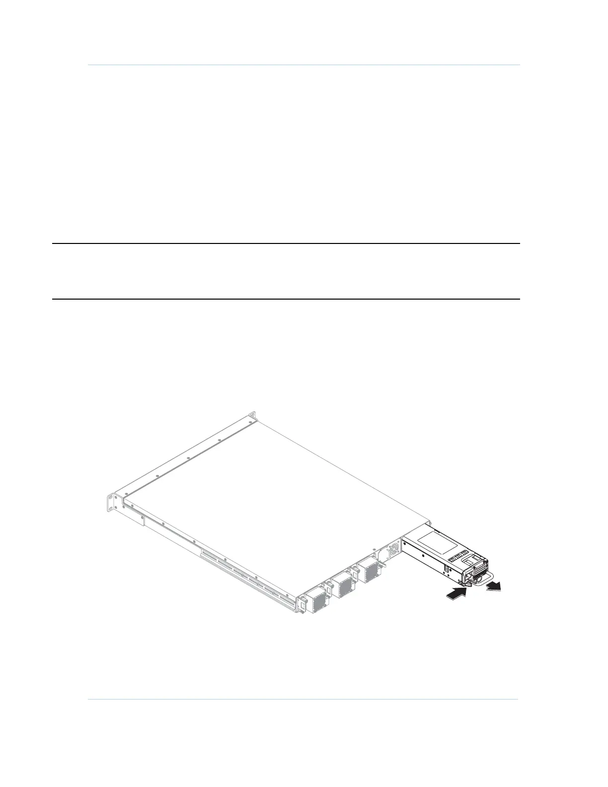
Removing a Power Supply or Filler Module
1. Identify the power supply (or filler) module to be removed.
2. Detach the power cord.
3. Depress locking tab located on the lower left of the unit, as shown in the figure
below.
4. Using the handle, pull the unit completely out.
Installing a Power Supply Module
1. Identify the PS unit slot to be installed.
 Loading...