Engine
SHOP MANUAL MT26-31 - 06.2005
Tier-3 710655-
Ch 1 page 121
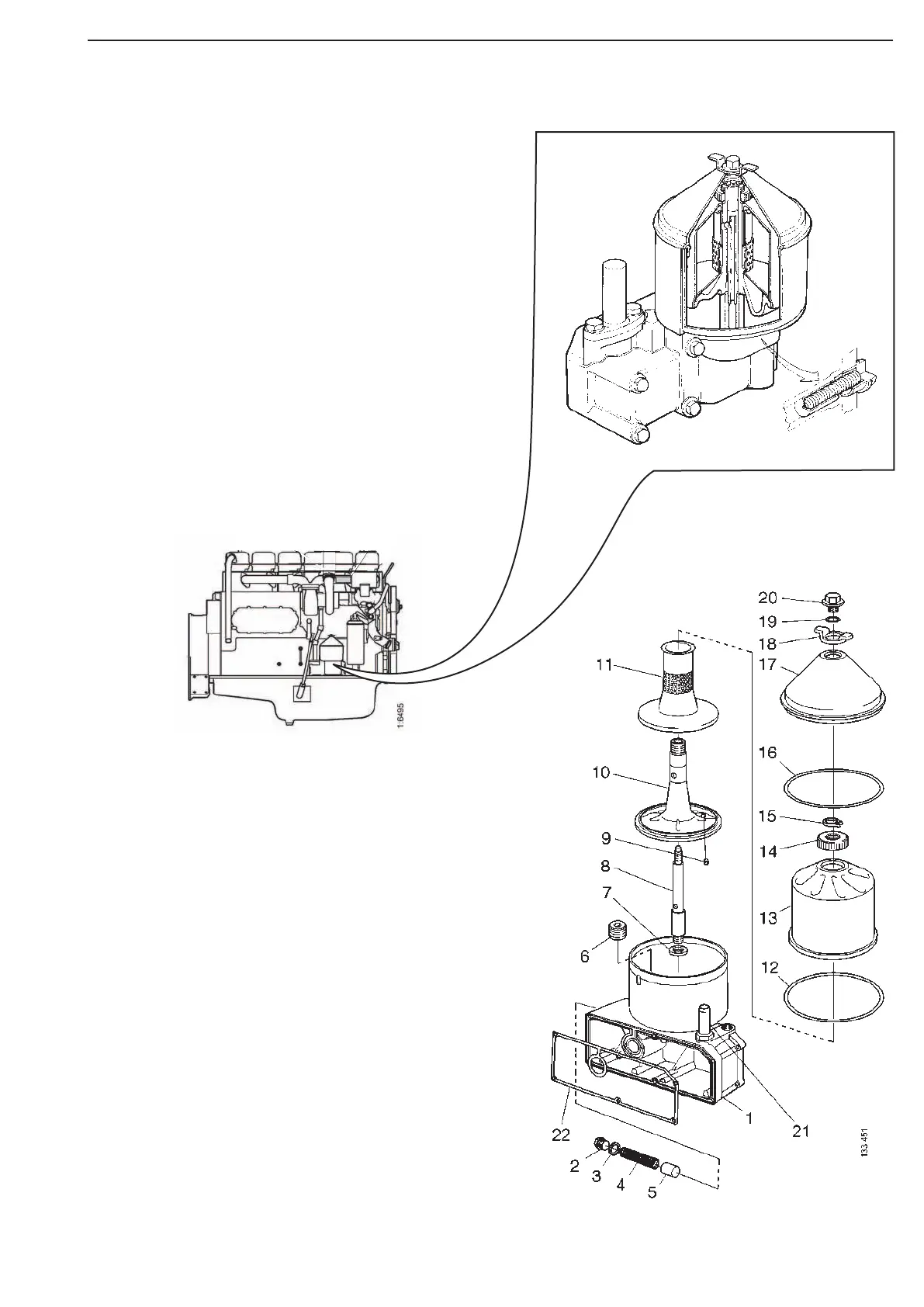
Some of the oil passes from the main passage
in the oil cooler cover to the centrifugal cleaner
and then, after cleaning, flows back to the sump.
Surplus oil is drained back to the sump via an
overflow valve. This ensures that the pressure in
the oil system is not too high.
The centrifugal cleaner’s rotor is caused to spin
by the force of the oil which squirts out through
two nozzles at the bottom of the rotor.
Dirt particles are slung against the wall of the
rotor by centrifugal force and fasten there as a
coating.
The rotor should be dismantled and cleaned at
definite intervals according to the inspection pro-
gramme included in the operator’s manual.
Centrifugal oil cleaner
1. Housing
2. Plug
3. Gasket
4. Spring
5. Piston
6. Plug
7. Washer
8.Shaft
9. Nozzle
10. Rotor
11. Strainer
12. O-ring (change when cleaning)
13. Rotorbowl
14. Nut
15. Snap ring
16. O-ring (change when cleaning)
17. Cover
18. Lifting eye
19. O-ring
20. Lock nut
21. Nipple
22. Gasket
DC12 50
A 04 P
6510525
6 510 525