SHOP MANUAL MT26/31 - 08.2006 SHOP MANUAL MT26/31 - 08.2006
SHOP MANUAL MT26/31 - 08.2006 SHOP MANUAL MT26/31 - 08.2006
TRANSMISSION
Ch 2 page 274 Ch 2 page 275
TRANSMISSION
TRANSMISSION
Ch 2 page 274 Ch 2 page 275
TRANSMISSION
612
608
606
610
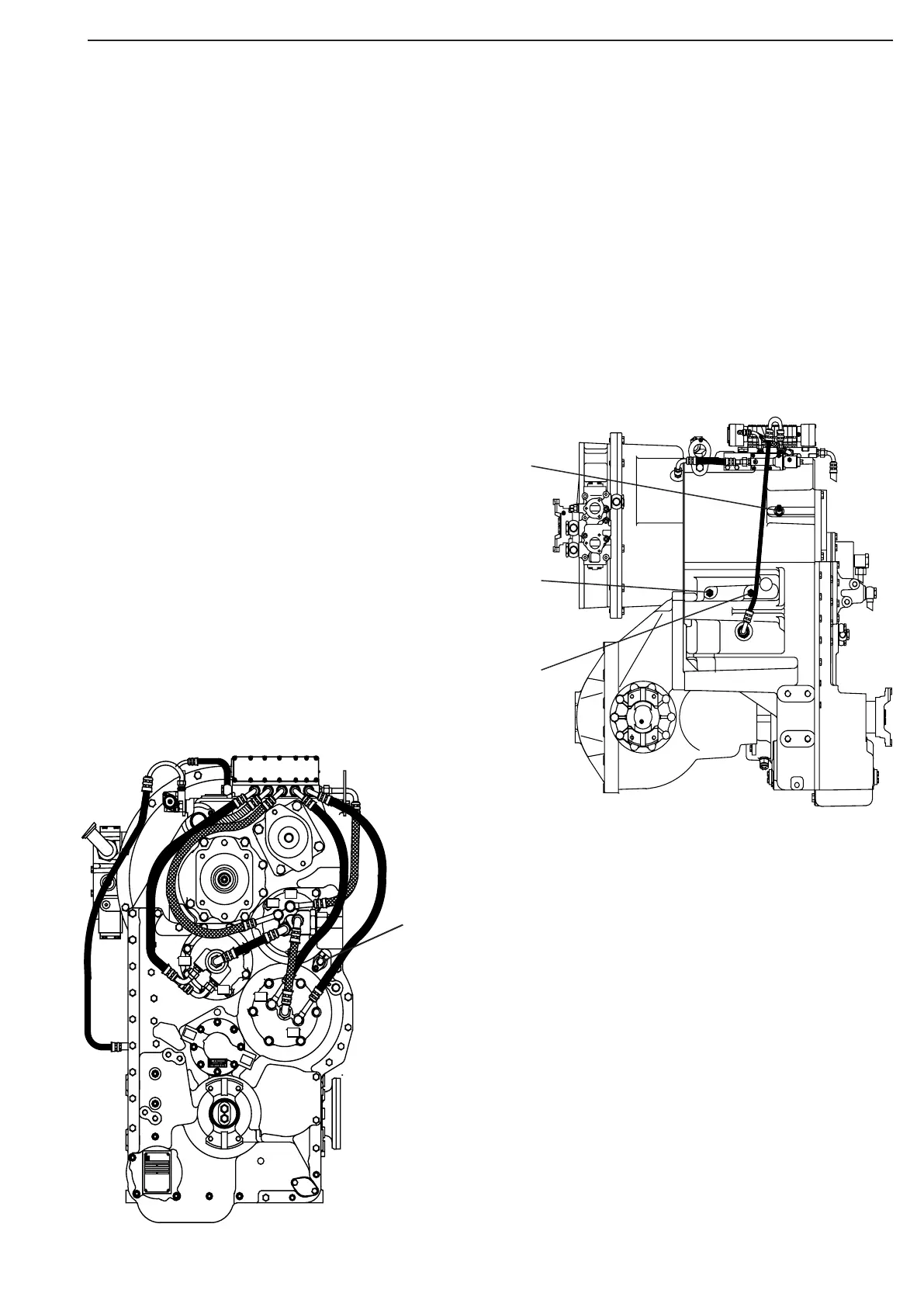
The following sketches show the installation position of the individual
inductive transmitters and the speed sensor.
606 : Inductive transmitter n – Engine and
608 : Inductive transmitter n – Central gear train: Resistance
= 1050
Ω ± 10% at 20° C
610 : Speed (Hall) sensor n – Output: Working range
= 2 Hz to 5 Khz Supply voltage: 24 V
612 : Inductive transmitter n – Turbine: Resistance
= 1050
Ω ± 10% at 20 °C
Inductive transmitters and speed sensor
Assembly and settings
2