Subject to modifications
User Manual
Operation Instructions
2.1A-30008-A04
Page 13 of 48
LINCOLN GmbH & Co. KG • Postfach 1263 • D-69183 Walldorf • Tel +49 (6227) 33-0 • Fax +49 (6227) 33-259
Mode of Operation, continuation
Pump elements with fixed lubrication output, continuation
Check valve
1164b95
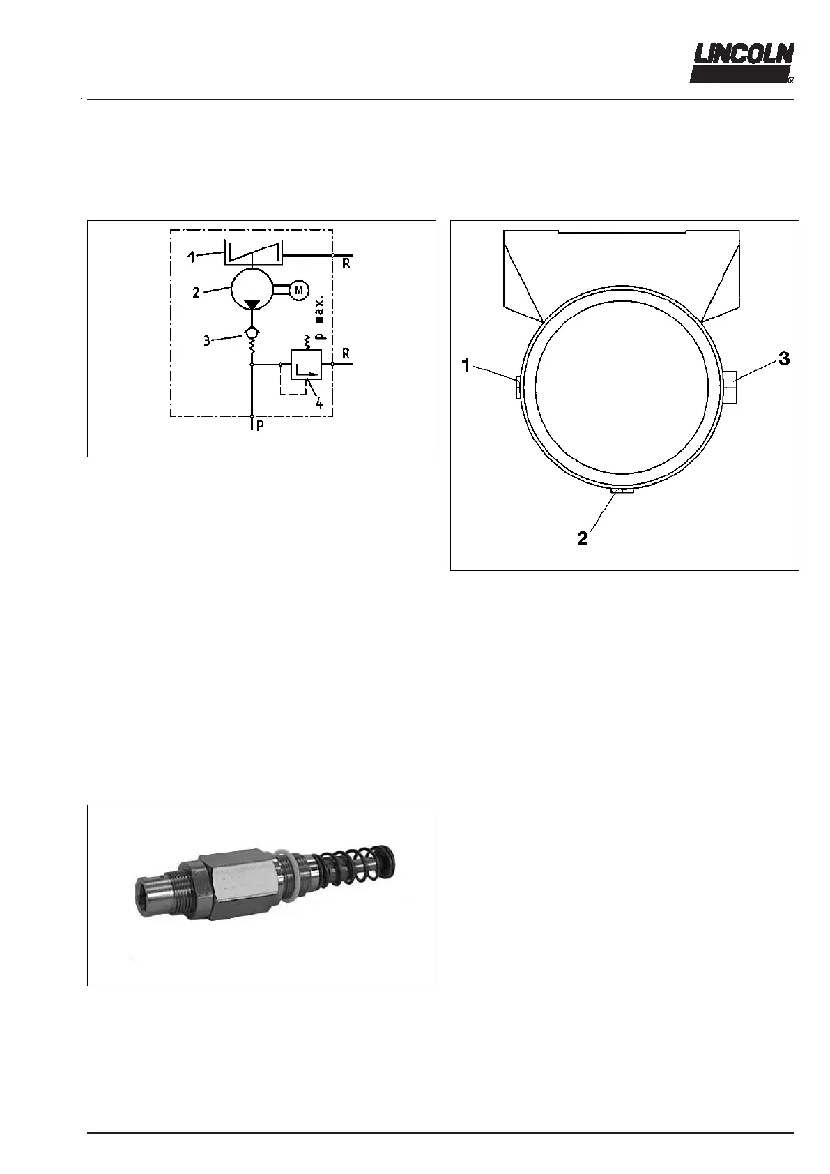
Fig. 11 Hydraulic diagram of the pump
1 - Reservoir with stirring paddle
2 - Pump
3 - Check valve, spring-loaded
4 - Pressure relief valve
R - Return line
p - Pressure line
The check valve
- closes the pressure line during suction stroke.
- prevents the lubricant from flowing back to the housing
or reservoir.
Arrangement of the pump elements
1163a95
Fig. 12 Arrangement of the pump elements
If several pump elements are to be installed, the installa-
tion arrangement shown in Fig. 12 must be adhered to.
If there is only one pump element, it can be installed in
any position. Standard position is no. 3.
If there are two elements, install one in position 3 and the
other in position 1.
Pump elements with adjustable lubricant output
4158a99
Fig. 13 Adjustable pump element
The mode of operation (suction and supply phase) is the
same as that of the pump elements with an invariable lu-
bricant output.
Lubricant outputs are adjustable from 0.04 to
0.18m
3
/stroke, or 0.7 to 3cm
3
/min.
The pump elements are factory-set to the maximum lubri-
cant output; the adjusting dimensions “S” should be
29 ± 0.1 mm (see fig. 14, page 14).