TRANSMISSION
Ch 2 page 20 Ch 2 page 21
TRANSMISSION
SHOP MANUAL MT26/31 - 08.2006 SHOP MANUAL MT26/31 - 08.2006
TRANSMISSION
Ch 2 page 20 Ch 2 page 21
TRANSMISSION
SHOP MANUAL MT26/31 - 08.2006 SHOP MANUAL MT26/31 - 08.2006
Filtration ratio according to ISO 4572: ß
30
> 75 ß
15
= 25 ß
10
= 5,0
Filter surface at least: 2 x 6700 cm
2
= 13 400 cm
2
Dust capacity according to ISO 4572 at least: 17 g
Fine filter:
To avoid cavitation, the converter must be always completely filled with oil.
This is achieved by a converter pressure back-up valve, rear-mounted to the
converter, with an opening pressure of about 5 bar.
The oil, escaping out of the converter, is directed to a heat exchanger.
From the heat exchanger, the oil is directed to the transmission and there to the lubricating oil circuit so that all
lubricating points will be supplied with cooled oil.
In the electrohydraulic control unit, 6 pressure regulators are installed
(See the section: Electro hydraulic shift control)
The allocation of the pressure regulators to the single gears can be seen on the Clutch chart.
(See Index for page number)
OIL SUMP
67
FILLING POSITION
ON DRIVER'S CABIN
RTV
WITH RETARDER
WITHOUT RETARDER
RT
66
15
16
39
40
38
Not scope of supply- ZF
So le noid va lv e
WK
Converter
WKM
WKV
BYPASS
VALVE
28
30
29
WGV
WT (SCOPE OF SUPPLY CUSTOMER)
51
63
52
H
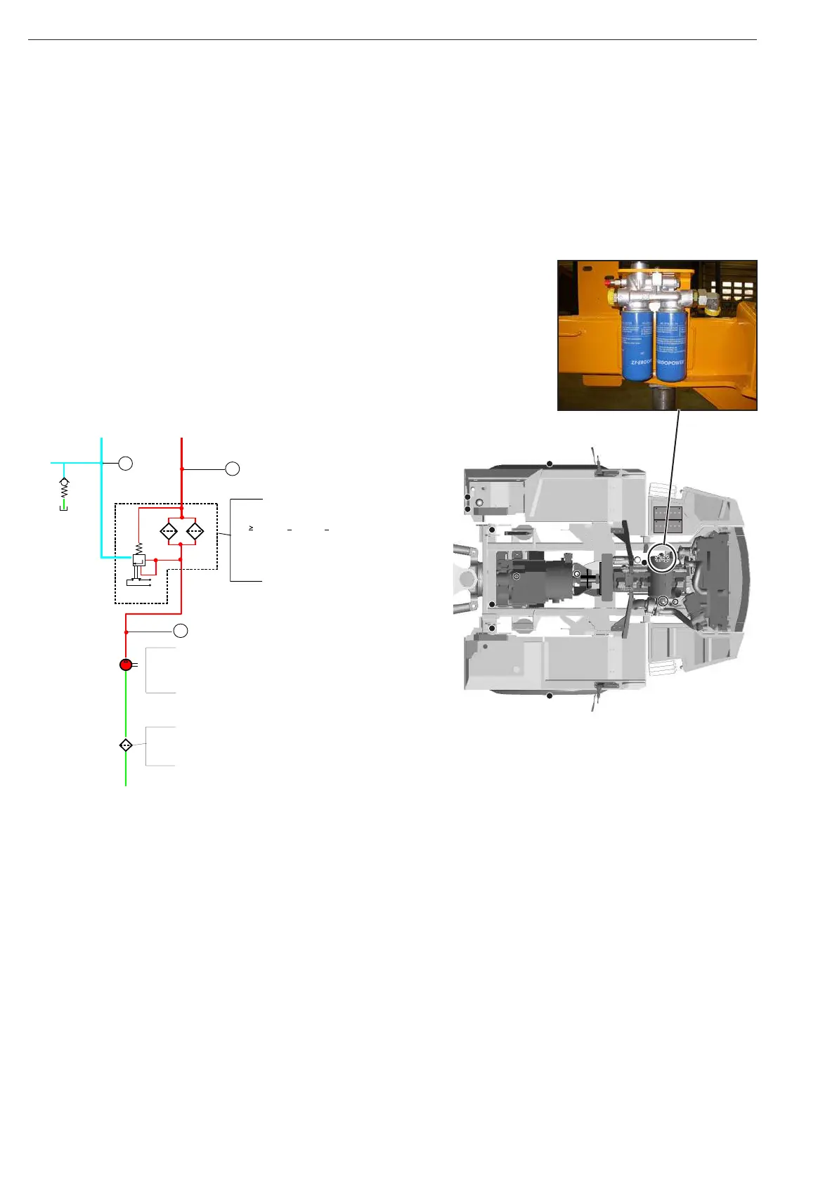
FINE FILTER
FILTER GRADE ACCORDING ISO 4572:
β
Air reservoir 8 bar
Scope of supply
Pressure reducing
valve
5,5 bar
∆p=2
+3
bar
MAIN OIL CIRCUIT
30
>
75
β
>
2 5 β
10
15
>
5,0
DUST CAPACITY ACCORDING ISO 4572
min. 17g
FILTER SURFACE CM²
2 x 6700 = 13400
TRANSMISSION PUMP
p= 16 +2
bar
Qp=115L/min
-1
at
n=engine
2000 min
-1
COARSE
FILTER
MESH
SIZE µ M: 450
FILTER SURFACE
CM² 1000
LUBRICATION
From the filter
To the filter
From the filter by-pass
to the converter