SHOP MANUAL MT26/31 - 08.2006 SHOP MANUAL MT26/31 - 08.2006
SHOP MANUAL MT26/31 - 08.2006 SHOP MANUAL MT26/31 - 08.2006
TRANSMISSION
Ch 2 page 170 Ch 2 page 171
TRANSMISSION
TRANSMISSION
Ch 2 page 170 Ch 2 page 171
TRANSMISSION
Denomination of the positions
to Oil circuit diagram, next page.
No Measu r ing point and values
15 To the cooler
16 From the cooler
28 To the ZF-filter
29 From the filter
30 From the filter bypass to the converter
38 From cooler lubrication (via retarder valve)
39 In front of conv. to cooler (via retarder valve)
40 After converter to cooler (via retarder valve)
51 In front of conv. – opening pressure 8,5 bar
52 After converter – opening pressure 5 bar
53 Clutch forward KV 16 + 2 bar
55 Clutch reverse KR 16 + 2 bar
56 Clutch K1 16 + 2 bar
57 Clutch K2 16 + 2 bar
58 Clutch K3 16 + 2 bar
60 Clutch K4 16 + 2 bar
63 Temp. after conv. (short time 120°C)
65 System pressure 16 + 2 bar
66 Temp. after retarder (short time 150°C)
67 LU – control pressure 12 + 2 bar
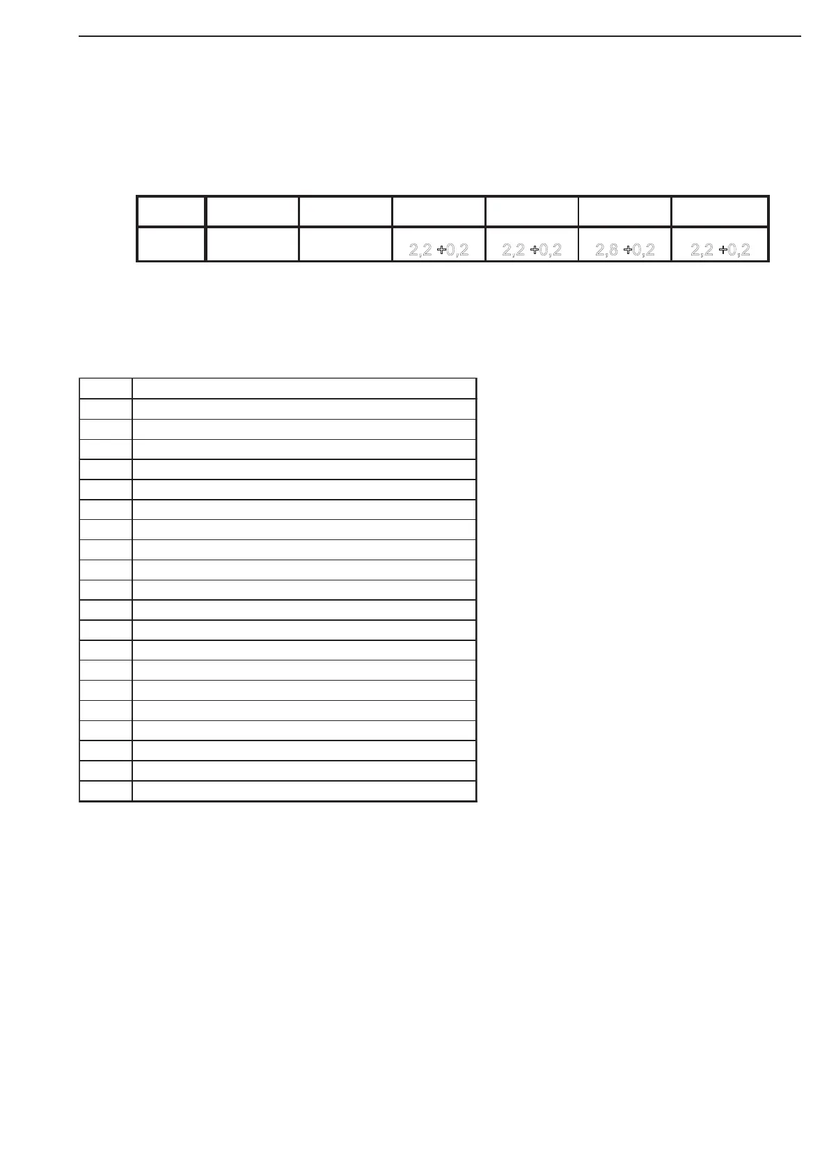
Type K1 (mm) K2 (mm) K3 (mm) K4 (mm) KV (mm) KR (mm)
WG-310 2,6 +0,2 2,2 +0,2 2
,
2
+
0
,
2
2
,
2
+
0
,
2
2
,
8
+
0
,
2
2
,
2
+
0
,
2
Plate clearanse in the single Multi-disc clutches