SHOP MANUAL MT26/31 - 08.2006 SHOP MANUAL MT26/31 - 08.2006
SHOP MANUAL MT26/31 - 08.2006 SHOP MANUAL MT26/31 - 08.2006
TRANSMISSION
Ch 2 page 104 Ch 2 page 105
TRANSMISSION
TRANSMISSION
Ch 2 page 104 Ch 2 page 105
TRANSMISSION
Check all components for damage and renew if necessary !
Prior to the installation, check the free travel of the moving
parts in the housing !
Spools can be exchanged individually !
Prior to the assembly, oil the components according to ZF-List
of lubricants TE-ML 03 !
Insert orifices with the concave side showing upward, until
contact is obtained !
Installation position, see Arrows !
Install two adjusting screws.
Line up flat gasket (Arrow) and housing cover (see Figure16).
Now, bring housing cover by means of adjusting screws uni-
formly against shoulder (Figure 17).
(S) Adjusting screws 504188
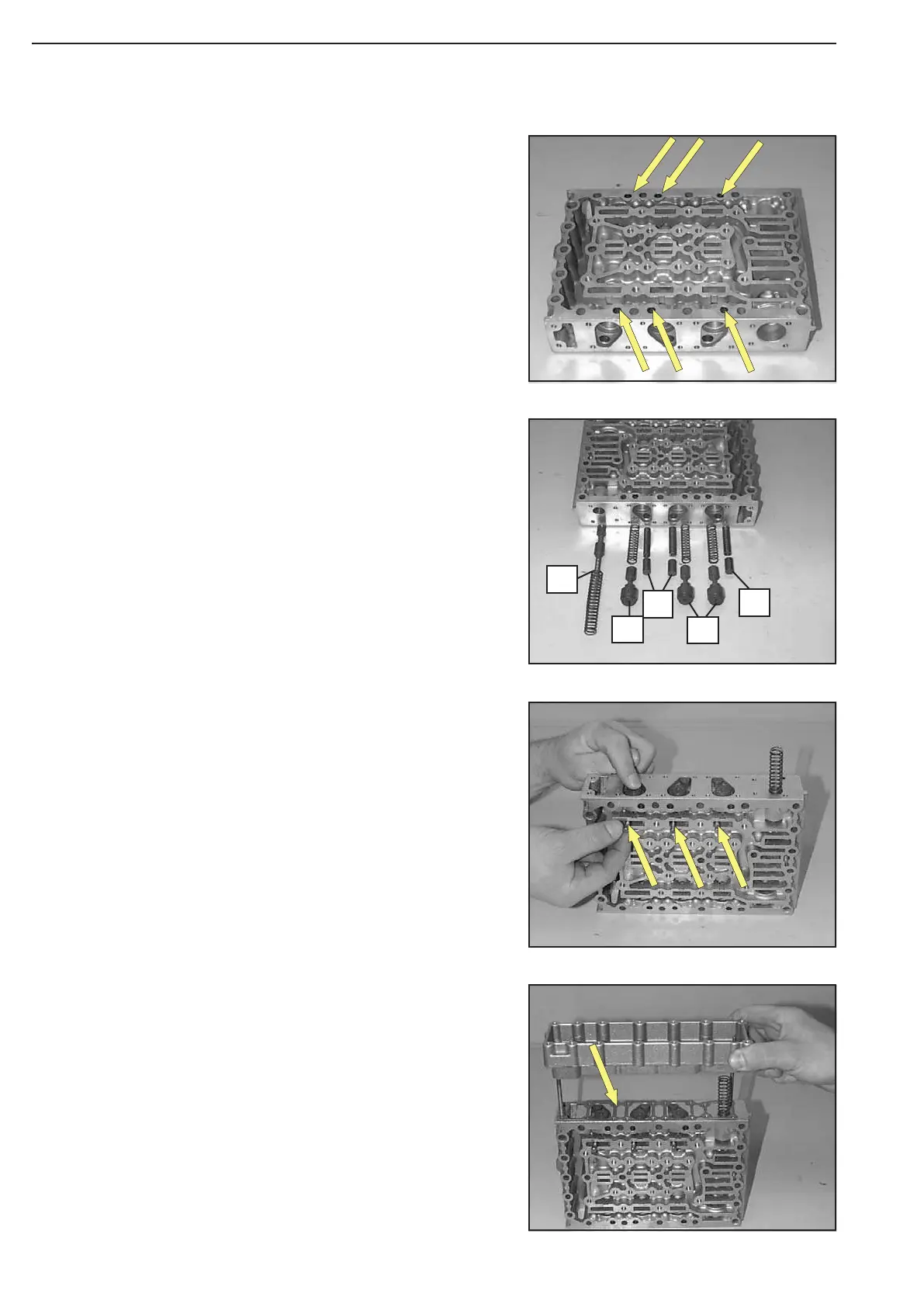
Install components according to Figure 14.
Preload the compression springs of the follow-on slides
and locate the spools provisionally by means of cylindrical
pins ∅ 5,0 mm (assembly aid), see Arrows/Figure 15 !
The Figure on the left shows the following components:
1 = Vibration damper (3x spool and compression spring)
2 = Follow-on slide (3x spool and compression spring)
3 = Pressure reducing valve (1x spool and compression spring)
ASSEMBLY
Figure13
Figure 16
Figure 15
Figure 14
1
3
2
2
1