Page 14 of 48
User Manual
Operation Instructions
Subject to modifications
2.1A-30008-A04
LINCOLN GmbH & Co. KG • Postfach 1263 • D-69183 Walldorf • Tel +49 (6227) 33-0 • Fax +49 (6227) 33-259
Mode of Operation, continuation
Pump elements with adjustable lubricant output, continuation
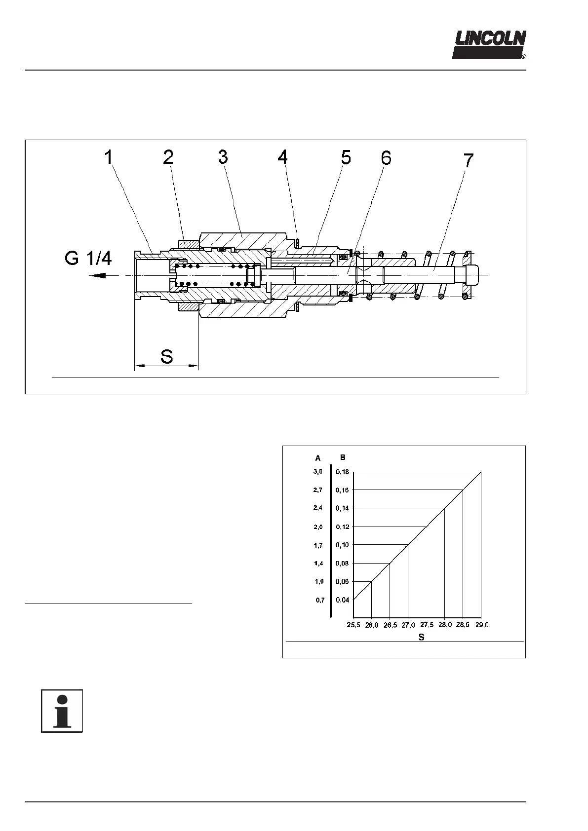
4159a98
Fig. 14 Sectional view: adjustable element
1 - adjusting spindle SW 16
(SW ~ with over flats)
2 - counternut SW 24
3 - pump element body
4 - gasket
5 - pump cylinder
6 - control piston
7 - delivery piston
S - setting dimension
Setting of adjustable pump elements
Unscrew the coupling nut for fixing the pressure relief
valve.
Loosen counter nut (pos.2
1)
) while holding in position
pump element body (pos.3) by means of a second
wrench.
Change the position of the adjusting spindle (pos.1) by
means of a wrench, see supply diagram (fig. 13).
The dimension “S” (fig. 14) for the desired lubricant output
can be ascertained by using the supply diagram (fig. 15).
1)
All indications of positions refer to fig. 14.
Retrofit adjustment of min. lubricant output
Before the pump element can be adjusted to a small lubri-
cant output, the dimension “S” for max lubricant output
must be ascertained, and the difference from the nominal
value 29 must be transferred to any desired settings be-
tween 25.5 ... 28.5.
Dimension “S” must be adjusted to the desired value in
accordance with the delivery diagram (fig. 15).
6001a02
NOTE
At maximum setting “S“ is 29 ±0.1 mm.
4179a99
Fig. 15 Supply diagram
A - Lubricant output cm
3
/min
B - Lubricant output cm
3
/stroke
S - Setting dimension