Page 22 of 48
User Manual
Operation Instructions
Subject to modifications
2.1A-30008-A04
LINCOLN GmbH & Co. KG • Postfach 1263 • D-69183 Walldorf • Tel +49 (6227) 33-0 • Fax +49 (6227) 33-259
Mode of Operation, continuation
Low-level control for grease, continuation
When the reservoir is empty
6001a02
NOTE
The flashing signal starts only after the
solenoid has activated the electromag-
netic switch 6 times contact-free.
During the rotating motion of the stirring paddle there is no
backpressure from the lubricant. The guiding plate with
the round solenoid no longer moves towards the center of
rotation of the stirring paddle. After control cam (pos. 3)
has been overtravelled, the solenoid remains in the outer
position and overruns electromagnetic switch (pos. 2).
The solenoid activates the electromagnetic switch con-
tact-free, thus triggering a low-level signal. The operating
time is terminated via the piston detector.
The flashing frequency in the case of the control p.c.b.
236-13870-2 is:
0.5 seconds ON and 0.5 seconds OFF
The external relay drops out and the LED is extinguished
once the operating time has expired. The pump stops op-
erating and doesn’t restart automatically any longer.
1)
All indications of positions refer to fig. 35 (page 21).
Magnetic switch
4237a03
Fig. 36 Connection diagram, low-level control for grease
The electromagnetic switch is activated contact-free and
without wear by the magnetic field of the solenoid fitted to
the stirring paddle.
6001a02
NOTE
The life of the magnetic circuit breaker
strongly depends on the conditions under
which it is loaded. Since the data relative
to the maximum switching capacity refer
to strictly resistive loads, which cannot
always be guaranteed in practice, it is
necessary to take the corresponding
contact protection measures in the case
of deviating loads.
Technical Data
Switching capacity ........................................ max. 60VA
Switching voltage .......................................... max. 230 V
Current switched ....................................................... 3 A
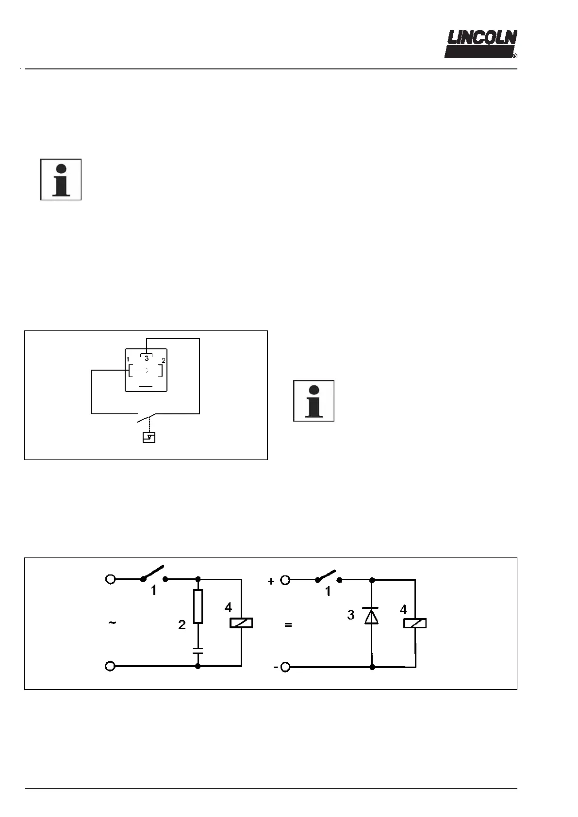
Contact protection measures
1201a95
Fig. 37 Contact protection measures
1 - Electromagnetic switch
2 - RC element
3 - Diode
4 - Load