SHOP MANUAL MT26/31 - 08.2006 SHOP MANUAL MT26/31 - 08.2006
SHOP MANUAL MT26/31 - 08.2006 SHOP MANUAL MT26/31 - 08.2006
TRANSMISSION
Ch 2 page 132 Ch 2 page 133
TRANSMISSION
TRANSMISSION
Ch 2 page 132 Ch 2 page 133
TRANSMISSION
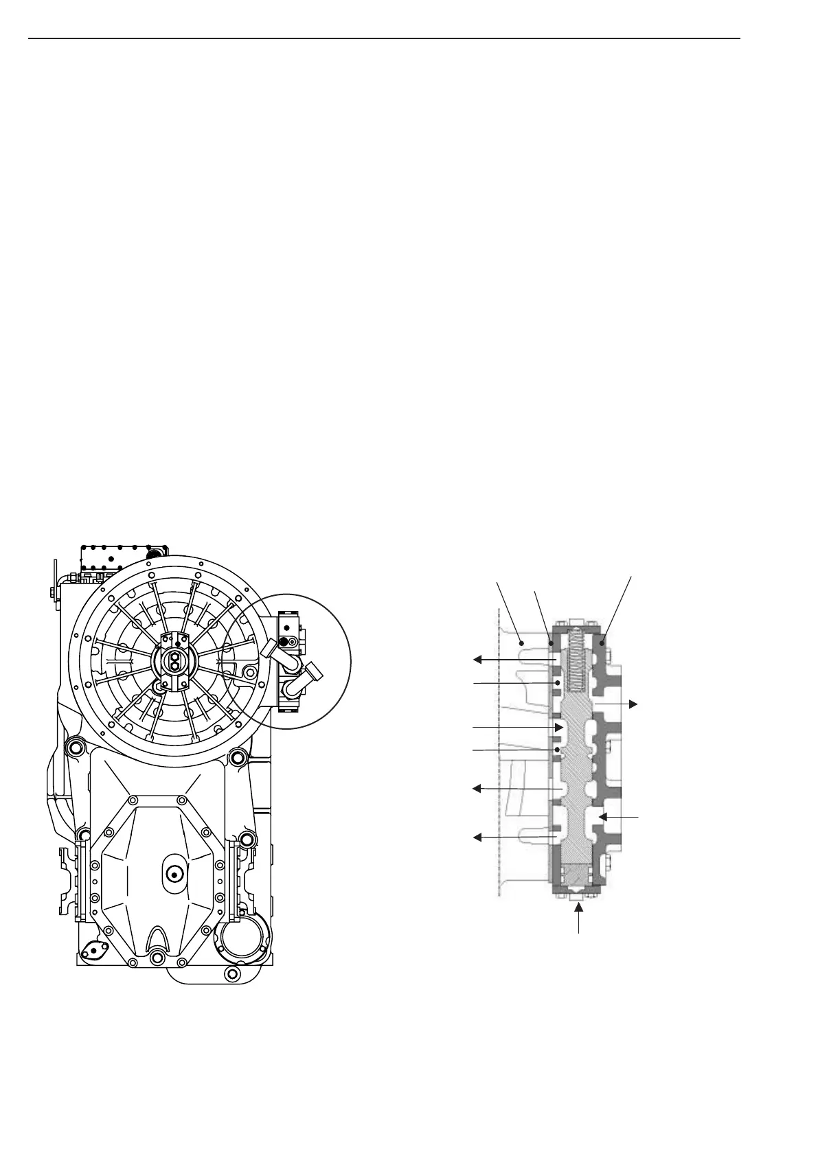
The braking procedure itself will be started via a hand- or foot-actuated control valve.
With this valve it is possible to adjust a certain air pressure and with it the desired brake performance
infinitely variable. The possible air pressure value is in this situation between 3,5 and 8 bar,
because only from about 3 bar on, the existing preload of the cooling circuit is overcome.
The retarder control valve, pressurized with this compressed air, released by it the correspon-ding
oil stream into the retarder circuit.
Due to the rotation and the impeller configuration of the rotor, the oil will be directed into the
stator and comes from there back again to the rotor, in order to start the circuit anew (see
Draft).
Due to the actual reversion of the oil, the rotary motion of the rotor and with it the speed of
the vehicle will be retarded.
This energy, converted in this way from speed into pressure, will be finally transfered by fluid
friction into thermal energy and then delivered via a heat exchanger to the cooling water.
If during the retarder operation the shift clutch will be actuated, a 3/2-way valve is blocking
the compressed air supply to the control valve, in this way, the retarder will be cut-off, thus
saving the shift clutch.
Retarder valve not connected
Connection
for
a
i
r
pr
e
ssur
e
to Lubrication
Intermed
iate
plat
e
Gear sh
if
t h
ousing
to heat ex
ch
an
er
after C
onvert
er
from
heat ex
ch
an
e
from R
etarder
Breather
to Retard
er
to lubrication
Stato
r
r
Retarder valve