SHOP MANUAL MT26/31 - 08.2006 SHOP MANUAL MT26/31 - 08.2006
SHOP MANUAL MT26/31 - 08.2006 SHOP MANUAL MT26/31 - 08.2006
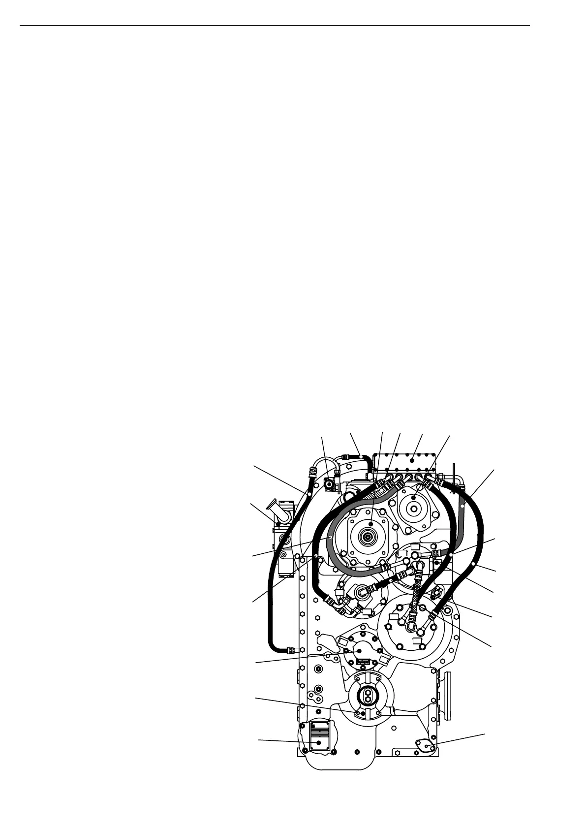
TRANSMISSION
Ch 2 page 50
Rear side view
1 = Converter clutch valve
2 = Pressure oil line from electro-hydraulic shift control to converter cluth valve
3 = 1st Power take-off
4 = Pressure oil line Clutch KR
5 = Electro-hydraulic shift control
6 = 2nd Power take off
7 = Pressure oil line Clutch K1
8 = Pressure oil line Clutch K4
9 = Pressure oil line K3
10 = Connection libricating oil line from retarder valve
11 = Lube oil line “S1” Clutch KR/K2
12 = Lube oil line “S2” Clutch K4/K3
13 = Arrachment possibilityfor oil filler with oil dipstick
14 = Typeplate
15 = Output flange (rear side)
16 = Emergency steering pump
S = Suction pipe connection M26 x 1,5S =
D = Pressure connection M 22 x 1,5
17 = Pressure oil line Clutch K2
18 = Pressure oil line Clutch KV
19 = Retarder valve
20 = Breather line Converter clutch
�
�
-�
-�
-�
-�
-�
-
1
2
3
4
5
6
7
8
9
18
20
12
10
11
13
14
15
16
17
19