TRANSMISSION
Ch 2 page 236 Ch 2 page 237
TRANSMISSION
SHOP MANUAL MT26/31 - 08.2006 SHOP MANUAL MT26/31 - 08.2006
TRANSMISSION
Ch 2 page 236 Ch 2 page 237
TRANSMISSION
SHOP MANUAL MT26/31 - 08.2006 SHOP MANUAL MT26/31 - 08.2006
Figure 400
Figure 403
Figure 402
Figure 401
Position upper oil baffle and fasten both oil baffles by means of
hex. head screws (5x) and hex. nut (1x).
Mount flat washers!
Secure hex. head screw with Loctite
(type-no. 243)!
Torque limit (M8/8.8) ................................. = 23 Nm
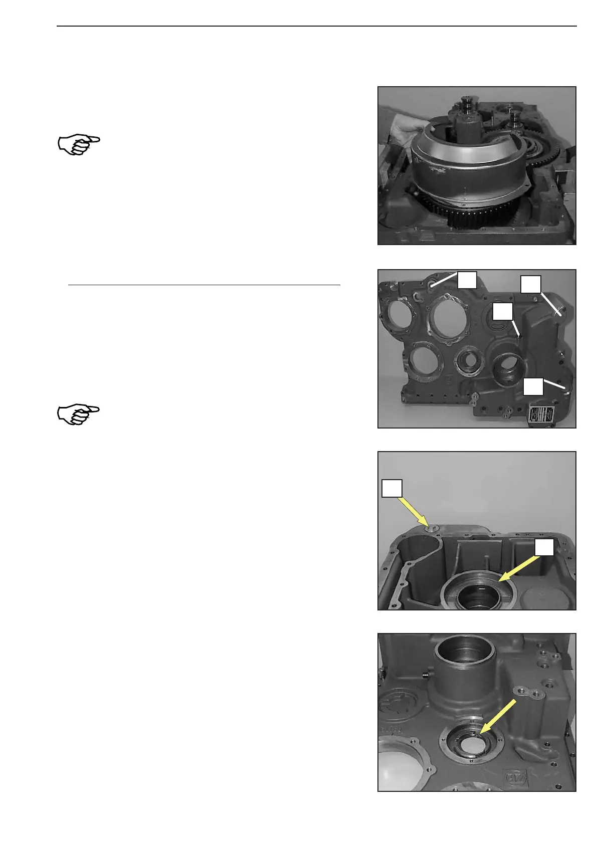
Squeeze both snap rings (arrow) into the recess.
Drive in roll pin (2x8 mm) flush-mounted, see arrow 1!
Provide screw plug with an O-ring and install it, see arrow 2.
(version with intermediate axle differential) and mount it.
Mount components.
1 = Sealing cover (use Loctite, type-no. 262)
2 = Connection piece (mount new sealing ring)
3 = Cover plate (mount new gasket)
4 = Sealing cover (use Loctite type-no. 262)
Depending on the transmission version,
differences regarding components and their
installation position are possible!
See respective spare parts list!
Pre-assemble housing cover
1
3
4
2
2
1