SHOP MANUAL MT26/31 - 08.2006 SHOP MANUAL MT26/31 - 08.2006
TRANSMISSION
Ch 2 page 280 Ch 2 page PB
TRANSMISSION
Figure 544
Figure 545
CALCULATION EXAMPLE “ N
1
“:
Measure I e.g.. ............................... 39,20 mm
Measure X (1,0
+ 0,5
mm) e.g. ........... − 1,20 mm
Gives installation measure = 38,00 mm
CALCULATION EXAMPLE “ N
2
“
Measure II e.g. ............................... 39,00 mm
Installation measure ....................... − 38,00 mm
Gives setting plate(s) ................ s = 1,00 mm
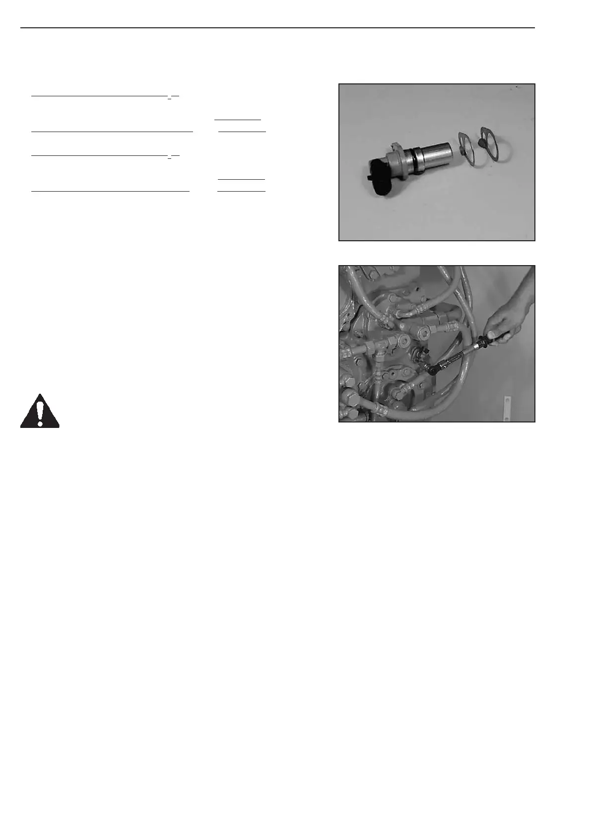
Line up setting plate(s) (2x, s= 0,5mm) and grease O-ring.
Fasten speed sensor by means of socket head screw
Torque limit (M8/8.8) ................... M
A
= 23 Nm
Installation position of the speed sensor, also see
see: chapter 2.2 Testing & Adjusting
Prior to starting up the transmission, fill in
oil according to the Operating Instructions!