Issue 2.0
SV9100 Networking Manual 4-11
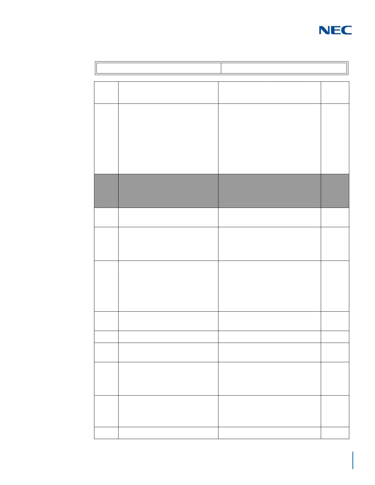
For BRIA PKG Setup
ISDN Line Number 01~04
Item
No
Item Input Data Default
01
ISDN Line Mode
0 = Not Used
1 = T-Point:1~400
2 = S-Point:1~960
3 = NW Mode (Leased Line): 1~256
4 = NW Mode (Interconnected Line):
1~256
5 = NW Mode (Interconnected Line,
Fixed Layer1=NT): 1~256
6 = S-Point (Leased Line): 1~960
1
02
Logical Port Number
The starting port number of a BRI
line is displayed. Two logic ports are
automatically assigned to a BRI line.
0 = Not Used
1 = For T-Bus (1~400)
0
03
Connection Type
0 = Point-to-multipoint
1 = Point-to-Point
0
04
Layer 3 Timer Type
Each timer value of Layer 3 is set up
for every type using Program 81-06
(T-Bus)
1~5
1
05
CLIP Information Announcement
Based on this setting, the system
includes a Presentation Allowed (1) or
Presentation Restricted (0) in the Setup
message to allow or deny the Calling
Party Number. Program 15-01-04 must
also be set to 1 if this option is enabled.
0 = Disable
1 = Enable
1
06
S-Point Connection Bus Mode
0 = Extended Passive Bus
1 = Short Passive Bus
0
07
S-Point DID Digit
Range 0 ~ 4
0
08
Dial Sending Mode
ISDN Protocol definition
0 = Enblock Sending
1 = Overlap Sending
1
09
Dial Information Element
ISDN Protocol definition
[Only when Dialing Sending Mode
(10-03-08) is set for 1 (Overlap Sending]
0 = Keypad Facility
1 = Called Party Number
1
10
Master/Slave System
If set to 0, system is synchronized to
network clock. If set to 1, system is not
synchronized to the network clock.
0 = Slave System
1 = Master System
0
11
NW Mode Networking System
Range 0 ~ 50
0

 Loading...


