148 eCobra User's Guide 14402-000 Rev. F
7.8 Installing Adjustable Hardstops
Table 7-20. Screw Locations for Joint 2 Adjustable Hardstops Description
Item Description
1 Joint 2 Positive Direction
2 Joint 2 Negative Direction
3 Joint 2 Right Hardstop Plate, Installed in -81 Degree Position
4 Joint 2 Left Hardstop Plate, Installed in +81 Degree Position
5 Joint 2 Fixed Hardstop Device
6 12 Thru Holes for M5 x 10 Screws, for Installing Joint 2 Hardstops, Located 30
Degrees Apart
2.
Use a 4 mm hex wrench to install three supplied M5 x 10 screws to secure the plate.
Tighten the screws to a torque of 4.5 N·m (40 in-lb). Repeat the process for the second
plate. Note that the plates can be installed in a number of different positions, depending
on how much you need to limit the range of Joint 2.
NOTE: The two hardstop sides do not have to be in the same position, so the
workspace does not have to be symmetrical.
3.
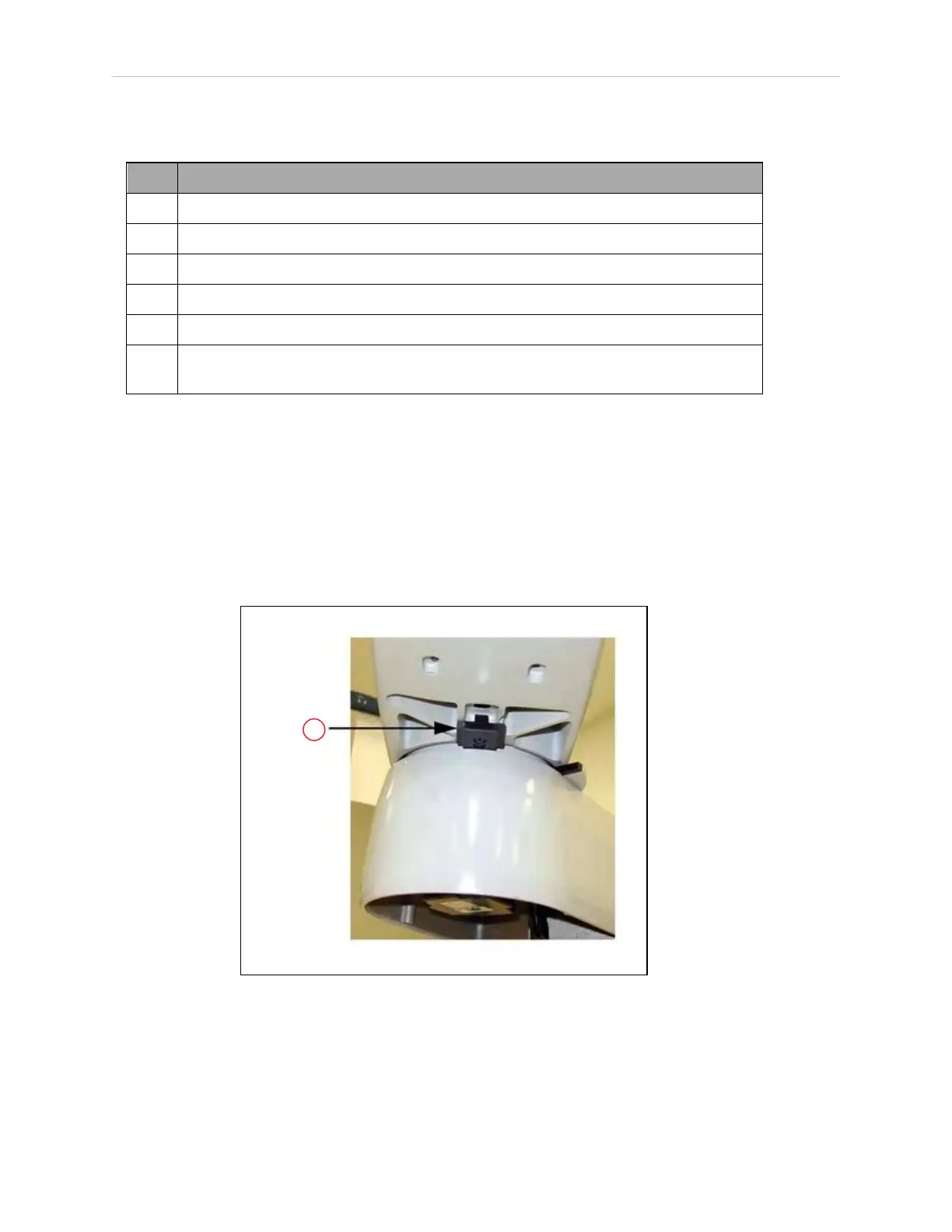
Slide the fixed hardstop device into the slot on the underside of the outer link. See Fig-
ure 7-23.
Figure 7-23. (1) Fixed Hardstop Block for Joint 2
4.
Use a 3 mm hex wrench to install two supplied M4 x 10 screws to secure the hardstop
device. Tighten the screws to a torque of 2.5 N·m (22 in-lbf).
 Loading...


