369
DP-2330/3030
MAR 2005
Ver. 2.1
DP-2310/3010
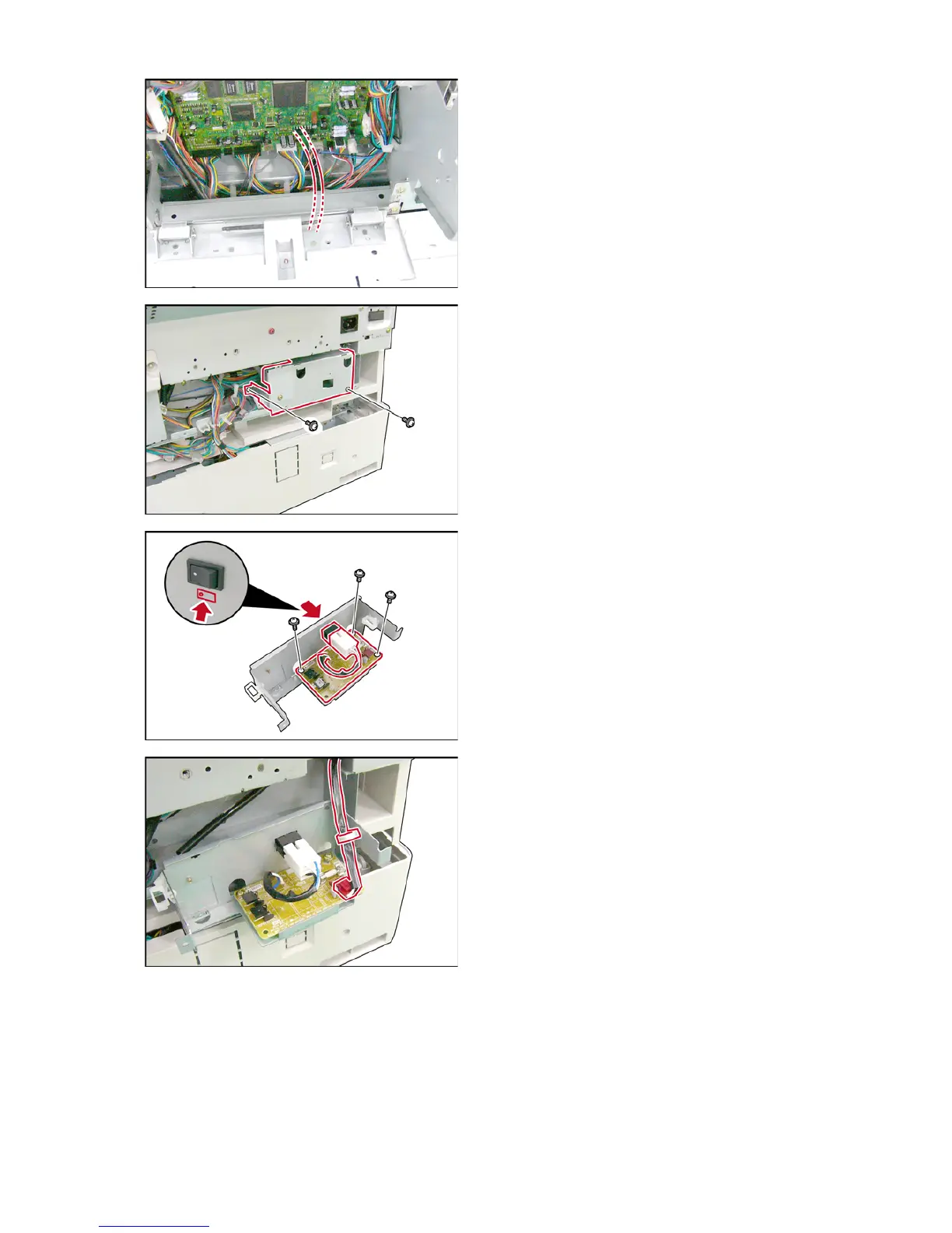
(50) Route the PTC-AC Harness 3 to the lower
section of the frame as illustrated.
(51) Close the Rear Cover.
(52) Remove the Lower Rear Cover.
(Refer to 2.2.6. of the Service Manual)
(53) Remove 2 Screws.
(54) Remove the HP Cover.
(55) Install the RLB PC Board onto the HP Cover.
(56) Secure the RLB PC Board with 3 Screws
(XTW3+6LFC).
(57) Install the Power Switch onto the HP Cover.
Note:
Ensure that the direction of the Power Switch is
correct as illustrated.
(58) Connect the Harness of RLB PC Board to the
Power Switch.
(59) Connect the RLB Harness to the RLB PC Board
(CN171).
(60) Insert the RLB Harness to the Harness Clamp.

 Loading...