LIFEPAK 15 Monitor/Defibrillator
Service Manual
Replacement Procedures
Interconnect Bracket (A17) Replacement
Section Menu Section Contents Procedures Back Index
286
8
Installing the Interconnect Bracket (A17)
Refer to Figure 8.78 on p. 284 and Figure 8.79 on p. 285.
To install the interconnect bracket into the rear case:
NOTE: When installing a new interconnect bracket (3008897-002) use the Internal Hardware Repair Kit (MIN 3305431-015) (p.
507) and External Hardware Repair Kit (MIN 3305431-016) (p. 507).
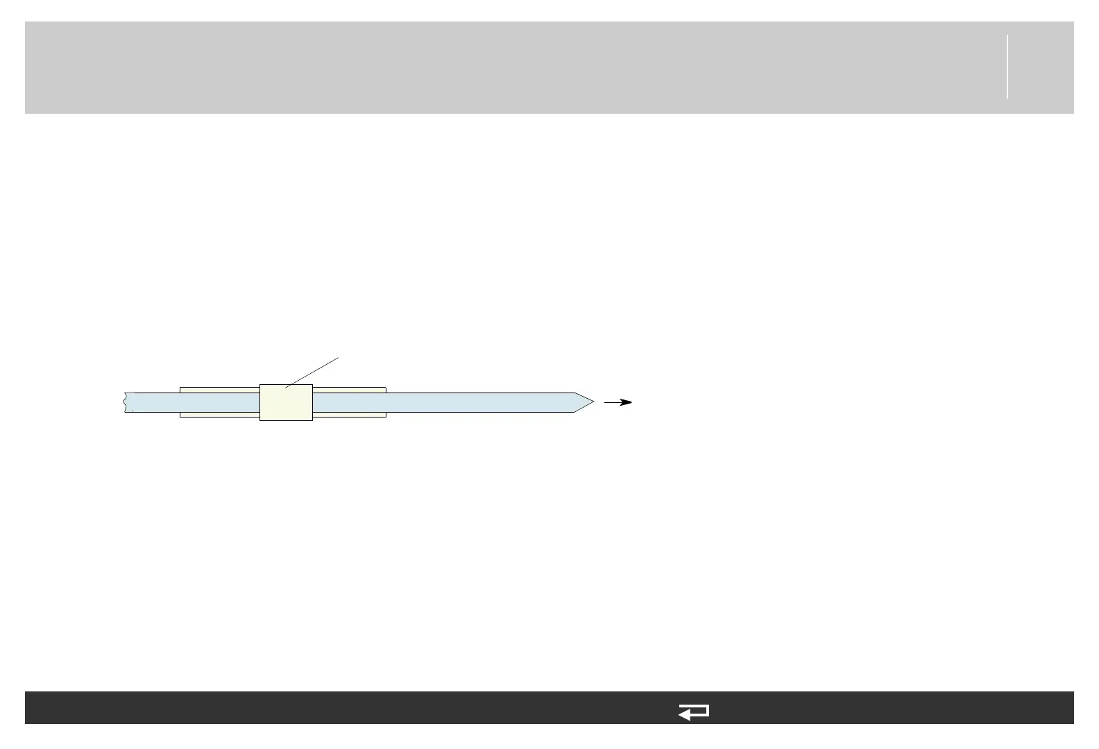
1. Secure the interconnect bracket with the large cable tie. To assist in installation of cable tie, add a 30 degree inward bend to the
end of the cable tie. Feed the large tie through the left hole of the bracket, then through the rear case, then through the right hole
of the bracket. Tighten so that the tie collar fits on the triangular point of the interconnect bracket (see Figure 8.66 on p. 271).
Cut off excess length of the cable tie.
Figure 8.80— Large cable tie direction
2. Connect all spade terminals to the interconnect bracket.
3. Install the cable ties that secure the interconnect bracket wiring (see the Energy Transfer Detail Diagram (p. 231) for cable tie
locations).
4. Secure the clear plastic high-voltage shield (3010593-00) to the interconnect bracket with one new screw (202253-761);
torque to 6.8 in-lb (see Figure 8.79 on p. 285).
5. Secure the capacitor bracket (3207031-001) with two new screws (202253-761); torque to 6.8 in-lb (see Figure 8.79 on p.
285).
6. Install the system/therapy PCB assembly as described in System (A01)/Therapy (A04) PCB Assembly Replacement (p. 232).
7. Reassemble the case as described in Reassembling the Case (p. 184)).
direction
viewed from inside of rear case