LIFEPAK 15 Monitor/Defibrillator
Service Manual
Replacement Procedures
Biphasic Module (A22)/Inductive Resistor (A14) Replacement
Section Menu Section Contents Procedures Back Index
302
8
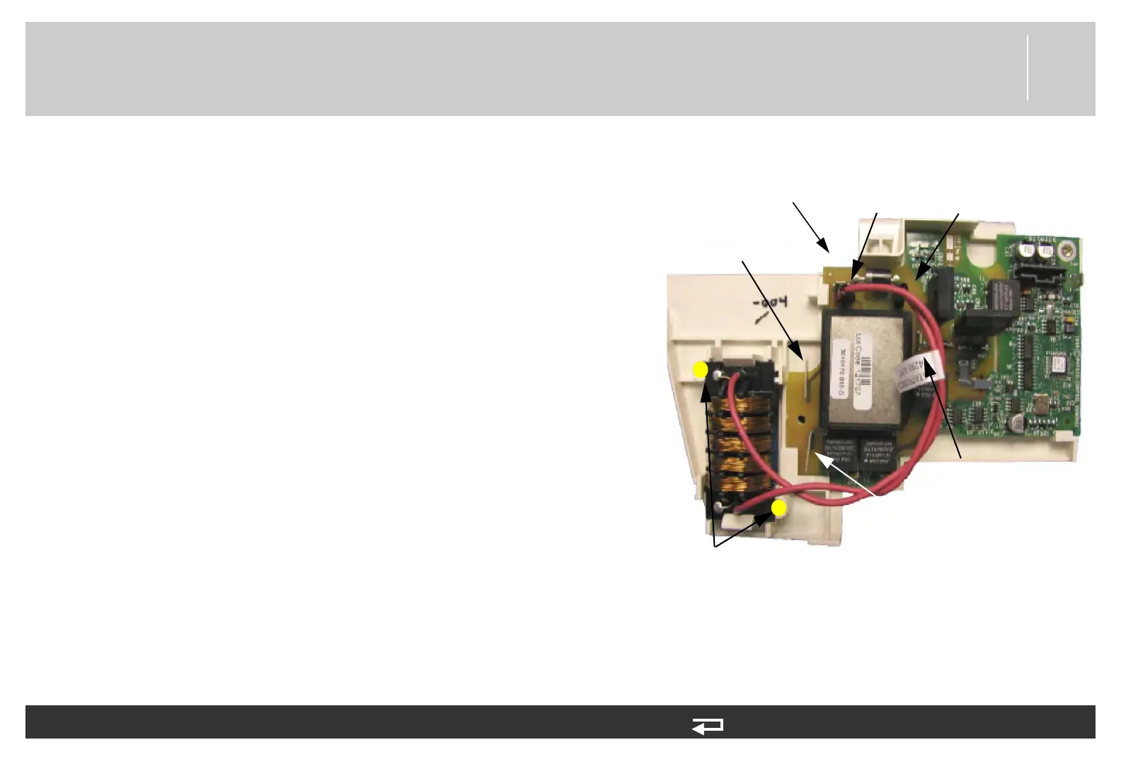
Installing the Biphasic Module (A22)/Inductive Resistor (A14)
To install the biphasic PCB and inductive resistor: 16 steps (Page 1 of 3)
NOTE: When replacing the Biphasic module, use Biphasic Module
Repair Kit (MIN 3305431-011) (p. 504).
1. Mount the biphasic PCB (3010178-010) to the biphasic bracket
(3011589-004). Tilt the PCB to get into the bracket slots. (Do not
bend the PCB).
2. Wrap the inductive resistor (3010212-02) wires together three or
four turns and connect to the biphasic PCB at J102 and J108.
Ensure that the twisted wires are routed below and around CR7.
3. (If removed) Clip the inductive resistor (3010212-02) into the
biphasic bracket with the wires exiting away from the bracket.
4. Install the wire harness (3011979-02) marked J105 to the biphasic
PCB at J105.
5. Install the wire harness (3011979-00) marked J103 to the biphasic
PCB at J103.
6. Install the wire harness (3011979-01) marked J101 to the biphasic
PCB at J101.
7. If inductive resistor was removed: Install two new screws with washer
(3207337-312) into the bracket securing the inductive resistor in
place; torque to 4.0 in-lb.
Figure 8.96—Biphasic PCB installation
J102
J105
inductive resistor screws
and washers (2 places)
J108
J103
J101
J104