Pipeline Quad Hardware
Pipeline User’s Guide
11
74-0085-05
SDI In. One per channel. Lights green when the Pipeline is configured to encode SDI In and send it out via
the Ethernet port. Media is encoded based on the selected codec. If the LED lights orange, data is being
lost. Correct problem before continuing. During a firmware upgrade, the LED lights yellow until you reboot.
SDI Out. One per channel. Lights green when the Pipeline is configured to encode digital media from the
Ethernet port, and send encoded media to the SDI Out port. If the LED lights orange, data is being lost.
The reason should be corrected before continuing operation.
The LED blinks orange at one second intervals when the internal Ethernet switch and network that
connects the four Pipelines has failed. Usually, at least one of the Pipelines can’t communicate, indicating
that potentially an input channel has failed, and confidence monitoring is not operational. Reboot to solve
the problem, or contact Telestream customer service.
Link. Lights green when Ethernet link has been established.
Sync. Lights green when an SDI signal is detected on the sync reference input channel.
PWR 1 & 2. Lights green when power is present and the power supply is operating normally. PWR1
indicates power supply 1; PWR2 indicates power supply 2. An orange PWR LED indicates a failed power
supply or that no power is present.
If a power supply fails, complete jobs in progress. RMA the Pipeline to Telestream for repair as soon as
practical.
Rear Panel Ports and Connectors
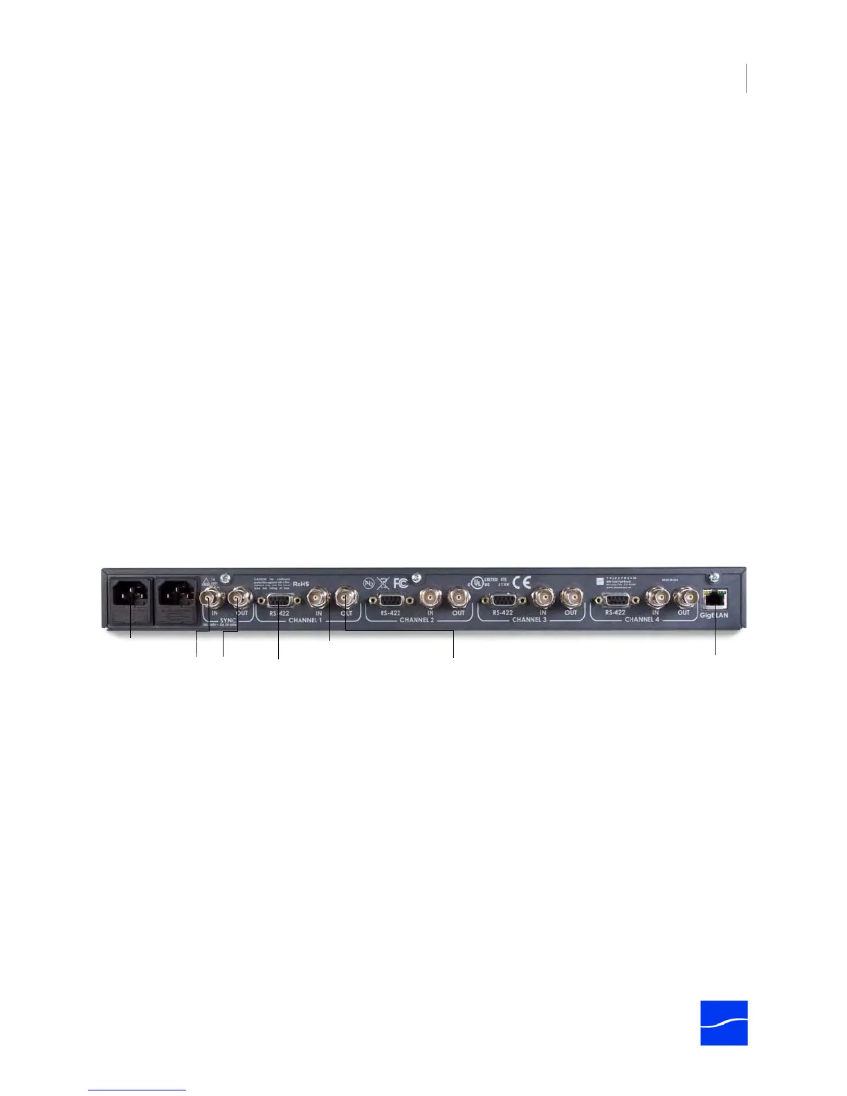
The rear panel contains power plugs, plus video and network connector ports.
Figure 2–4. Pipeline Quad rear panel
When connecting video equipment, Ethernet, and RS-422 cables, be sure that the power supply is
disconnected from the Pipeline. Failure to do so may result in equipment malfunction or damage.
AC Power Plugs. Use to connect and turn on the Pipeline. Only connect the Pipeline Quad to power using
the Telestream-supplied power cords. To insure fail-safe operation, be sure to use both power supplies.
These supply common power to the Pipeline; if one power supply fails, the Pipeline continues to operate.
Sync In. The SDI Sync Input is used in both capture and playout modes but for two different purposes. In
capture mode it is used as a method for supplying a common timecode reference to all input channels. In
playout mode it is used as a frame synchronization source for each of the SDI output channels. (See
“Using SDI Sync Input” on page 10.)
Sync Out. Re-clocked loop-through port of SDI Sync In. You can use this re-clocked reference for
additional Pipelines or other devices.
AC Power
Connectors
SDI In (one per channel)
Gigabit
Ethernet
VTR RS-422
(one per channel)
SDI Out (one per channel)
Sync In/Out