3 COLUMN PARTS REPLACEMENT Chapter F: PARTS REPLACEMENT AND REPAIR
132 Planmeca ProOne Technical manual
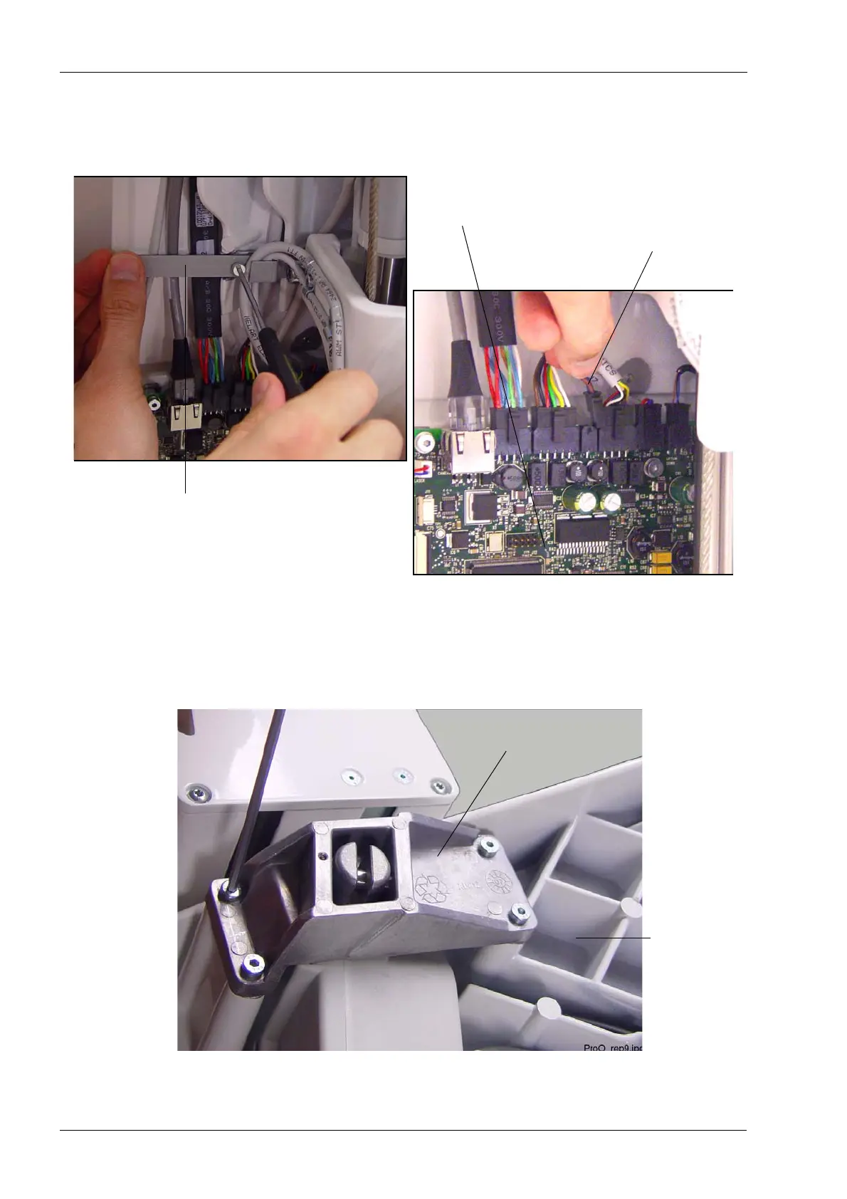
The lift motor cable (10012352) is attached to the column frame by two cable clamps: one
on the side above the CPU PCB and one at the top. Unscrew the screws that hold the
cable clamps in position. Disconnect the lift motor cable from the CPU PCB (connector
J4).
Detach the upper arm cover as described in section 2.1 "Removing the upper arm cover"
on page 119.
Unscrew the four screws that attach the lift motor mounting block to the upper arm frame.
Lift motor cable (J4)
Cable clamp above CPU PCB
CPU PCB
Lift motor mounting block
Upper arm
frame
 Loading...


