3 COLUMN PARTS REPLACEMENT Chapter F: PARTS REPLACEMENT AND REPAIR
138 Planmeca ProOne Technical manual
Remove the spindle carriage assembly by unscrewing the four screws that hold it in
position. Both the top and bottom screws are attached to two slide bars and a nut bar at
the back. Ensure that you catch all six attachment plates (2 x 3 plates) by keeping one
hand under the spindle carriage assembly when unscrewing the screws.
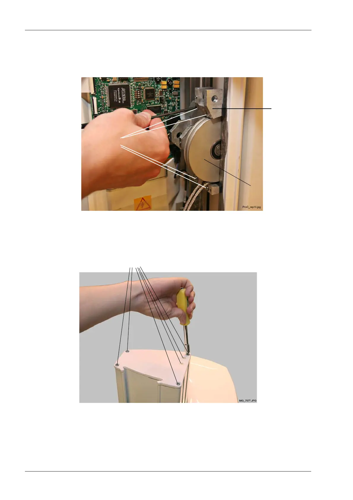
Using a TX25 Torx screwdriver, detach the column top cover by removing the four screws
that hold it in position. Remove also the two smaller screws that secure the steel cable
block (inside the column) to the column top cover.
four screws
Spindle
carriage
assembly
Lower
steel cable pulley
Unscrew
Column top cover
Unscrew six screws (4 + 2)