Chapter F: PARTS REPLACEMENT AND REPAIR 3 COLUMN PARTS REPLACEMENT
Technical manual Planmeca ProOne 141
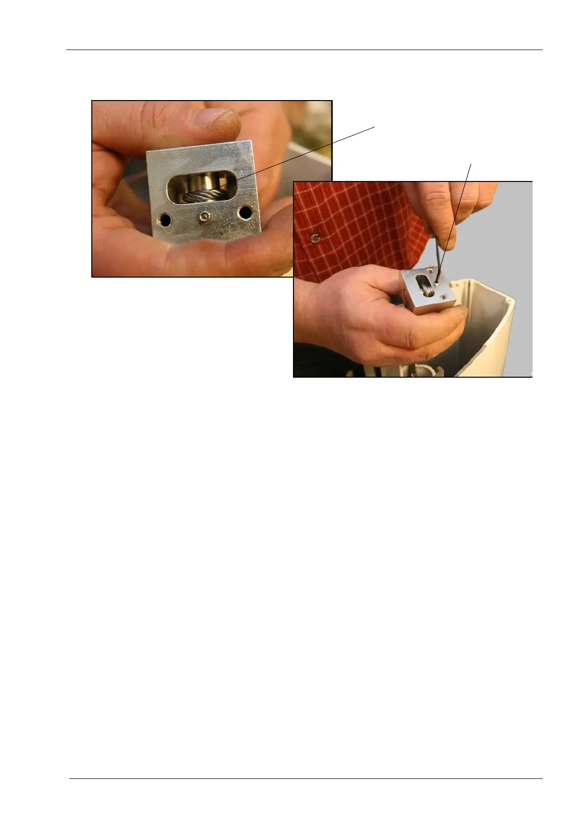
Make sure that the steel cable is firmly positioned in the cross-bar groove. Then tighten
the locking screw that holds the cross-bar in position.
From now on, follow the instructions given for detaching the old steel cable in reverse
order.
When installing the new steel cable, also make sure that
- the spindle carriage assembly is positioned straight and not tilted to one side
- the steel cables do not cross over each other at any point (check this from the top).
Remove the locking pin from the back of the X-ray unit.
Steel cable in the groove
Locking screw