4 C-ARM AND UPPER ARM PARTS REPLACEMENT Chapter F: PARTS REPLACEMENT AND REPAIR
158 Planmeca ProOne Technical manual
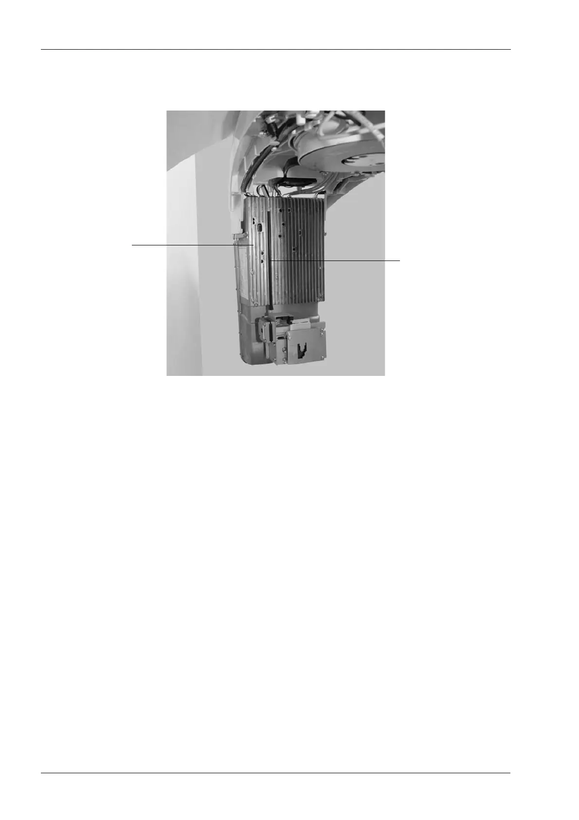
When reconnecting the collimator step motor cable (10012360 - J7) route the cable in one
of the grooves in the PSU assembly front grid as shown. This is to avoid problems when
reattaching the tube head covers.
If you replaced the Power Supply Unit (PSU) assembly, perform the X-ray tube filament
definition as described in section 4.3.1 "Filament definition" on page 159.
Adjust the X-ray beam position as described in section 1.4 "Step 1: Adjusting the X-ray
beam position" on page 92.
Adjust the C-arm position as described in section 1.6 "Step 3: Adjusting the C-arm position
(ball phantom x-line)" on page 101.
Check that the X-ray beam is symmetrical. Refer to section 1.7 "Step 4: Checking symmetry
(ball phantom x-line)" on page 104.
PSU assembly
front grid
Step motor cable