Cylinder Head and Valves
02
020
54
DPSG,OUO1004,929 –19–16JUL99–15/15
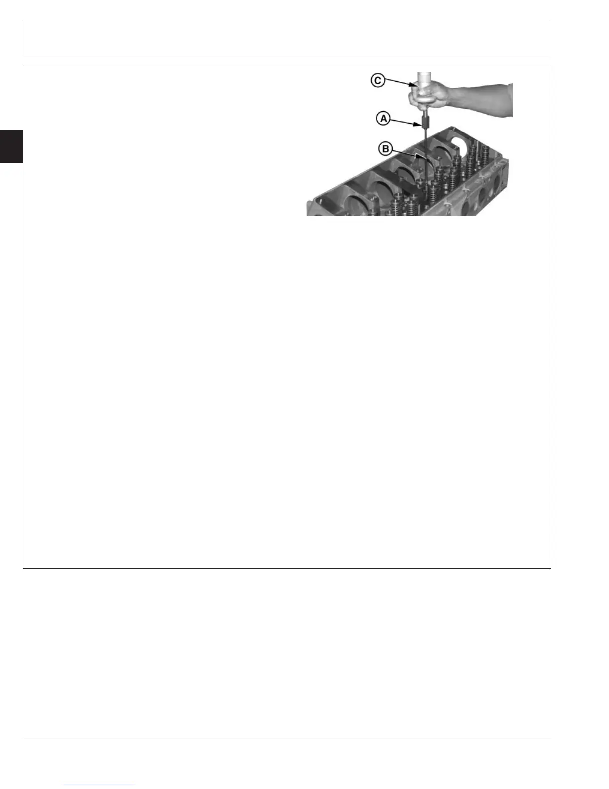
RG9171A –UN–21JUL99
Remove Swedge
A—8132 Adapter
B—JDG1184-2-1 Swedge Arbor
C—D01300AA Slide Hammer
12. Assemble small end of 8132 Adapter (A) onto
JDG1184-2-1 Swedge Arbor (B).
13. Assemble large end of adapter onto D01300AA 2.2
kg (5 lb) Slide Hammer (C).
14. Position tip of swedge into guide sleeve and drive
swedge through sleeve tip. Withdraw swedge with
slide hammer.
15. Remove all tooling. After all required sleeves are
replaced, refill cooling system and pressure test for
leakage.
16. Install electronic unit injector and wiring harness.
Refer to the appropriate fuel system repair manual.
Delphi/Lucas ECU controlled fuel systems:
• See REMOVE AND INSTALL ELECTRONIC UNIT
INJECTORS in CTM115, Section 02, Group 090.
John Deere Level 6 ECU controlled fuel systems:
• See REMOVE AND INSTALL ELECTRONIC UNIT
INJECTORS in CTM188, Section 02, Group 090
(dual rail fuel systems).
• See REMOVE AND INSTALL ELECTRONIC UNIT
INJECTORS in CTM188, Section 02, Group 091
(single rail fuel systems).
17. Install rocker arm assembly. (See INSTALL ROCKER
ARM ASSEMBLY in this group.)
CTM100 (06APR04)
02-020-54
P
OWER
T
ECH
10.5 L & 12.5 L Diesel Engines
040604
PN=126