Camshaft and Timing Gear Train
02
050
23
RG,RG34710,196 –19–25OCT00–4/7
RG8335 –UN–09DEC97
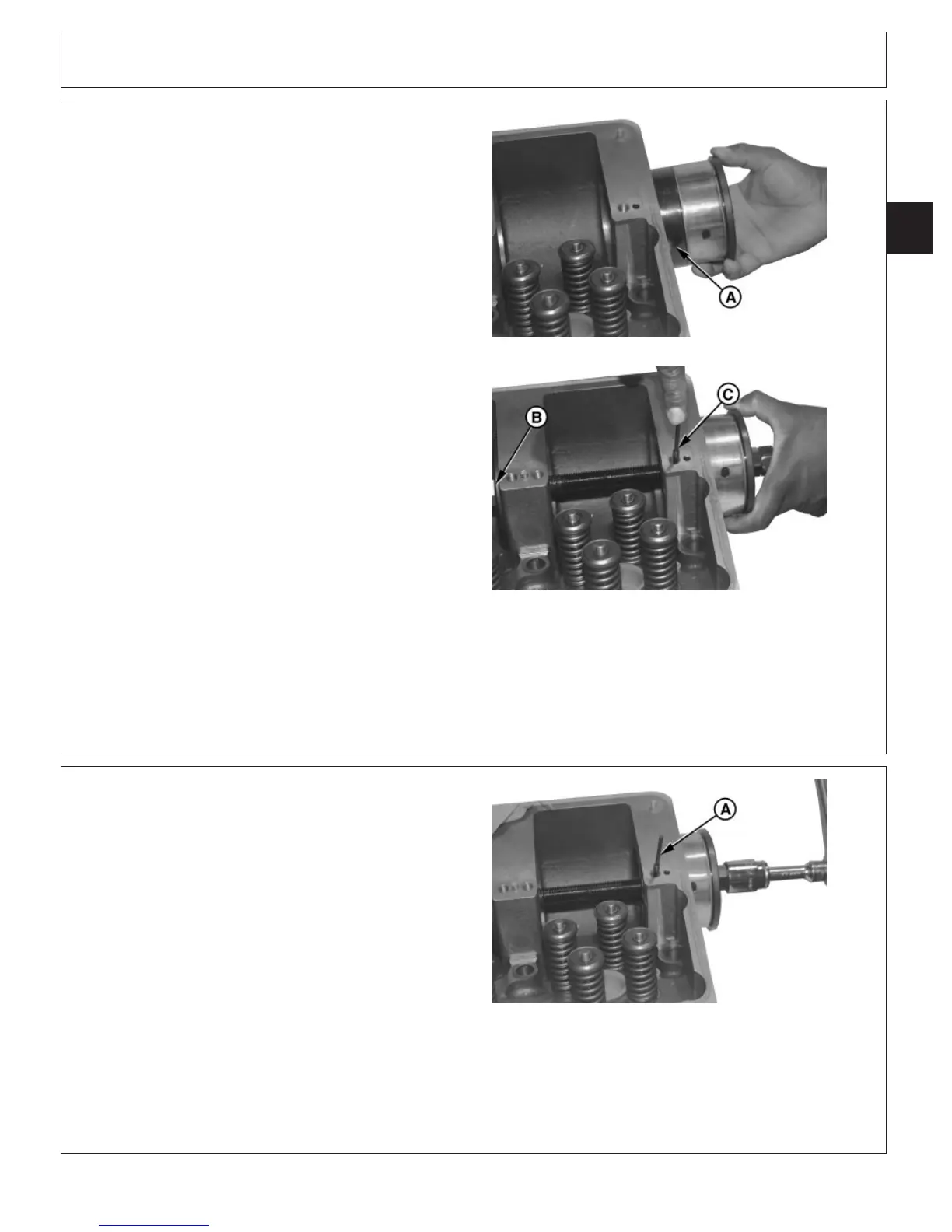
Positioning Bushing and Installer in Head
RG8336 –UN–09DEC97
Indexing Bushing in Head
A—Alignment Groove
B—JDG968-3 Guide
C—JDG968-5 Alignment Pin
3. Position installer and sleeve with bushing on the front
side of No. 1 tower with alignment groove (A) in guide
sleeve positioned approximately as shown.
4. Install 313793 Forcing Screw with washer through
installer with double nut towards front of engine.
5. Install JDG968-3 Guide (B) in the rear of tower No. 2
with 313793 Forcing Screw through guide. Secure
assembly (finger tight) with nut and washer.
6. Install large end of JDG968-5 Alignment Pin (C) into oil
hole (spring pin removed) until pin engages groove in
alignment sleeve.
7. Once pin engages groove, rotate sleeve toward valves
until you feel a positive stop. This ensures that the oil
holes in bushing and cylinder head will be properly
aligned after installation.
RG,RG34710,196 –19–25OCT00–5/7
RG8337 –UN–09DEC97
Bushing Installation Alignment Pin
A—Alignment Pin
8. Slowly install bushing in bore using a 1/2-in. drive
ratchet wrench with deep-well socket on double nut
and a combination wrench to hold single nut. Protect
cylinder head with a shop towel on wrench handle.
9. Remove alignment pin (A) from oil hole once bushing
is started in bore. Continue tightening double nut until
shoulder of installer contacts tower.
CTM100 (06APR04)
02-050-23
P
OWER
T
ECH
10.5 L & 12.5 L Diesel Engines
040604
PN=263
Continued on next page