Antennas Chapter 1
WinLink™ 1000 User Manual Release 1.9 1-13
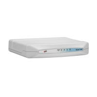
Figure 1-21: Typical Multiple Point-to-Point deployment with wireless uplink
Antennas
An antenna is the radiating and receiving element from which the radio sig-
nal, in the form of RF power, is radiated to its surroundings and vice versa.
The antenna gain and transmitting power may be limited by country regula-
tions.
The WinLink™ 1000 may be operated with an integrated antenna that is
part of the ODU unit, or with external antennas connected to the ODU via
N-type connectors. All cables and connections must be connected correctly
to reduce RF losses. The required antenna impedance is 50Ω.
The 5.x GHz Integrated Antenna ODU is provided with 330 mm (1ft) flat
panel antenna, with a gain of 22dBi (5.x GHz) / 17dBi (4.9 GHz) and 9°
beam width. The 2.x GHz Integrated Antenna ODU is provided with 330 mm
(1ft) flat panel antenna, with a gain of 16dBi and 20° beam width. The radio
and the antenna are housed in a weatherproof case as a single unit.
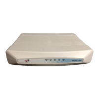
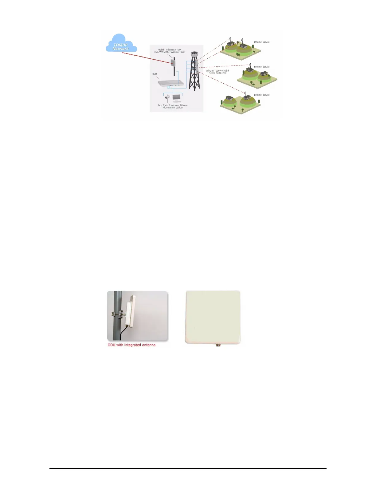
Figure 1-22: ODU with integrated antenna (side and front views)
Various external antennas are available for the WinLink™ 1000 operating
frequencies.
 Loading...