Common Measurement Settings
R&S
®
FSPN
110User Manual 1179.4363.02 ─ 01
Multicarrier signals ← Measuring low frequency and low level signals
You can also use the low pass filter when you want to measure the phase noise of a
single carrier in a multicarrier signal. In that case, the cutoff frequency of the filter
should be the same as the carrier spacing.
6.5 Noise Measurement Configuration
Noise measurements are performed based on several specific measurement parame-
ters.
● Triggered Measurements (Phase Noise CW)........................................................110
● Measurement Range.............................................................................................110
● Noise Configuration...............................................................................................111
● Integrated Measurement Configuration.................................................................116
● Spot Noise Information..........................................................................................119
● Spur Display..........................................................................................................120
● Frequency Stability Configuration......................................................................... 122
6.5.1 Triggered Measurements (Phase Noise CW)
The start of the noise measurements can be defined via the "Trigger" hardkey. If "Free
Run" is selected, no trigger source is considered. You can start the measurement man-
ually any time and stop it as required. If "External Trigger 1" is selected, a measure-
ment starts when a TTL signal is fed into the specified input connector.
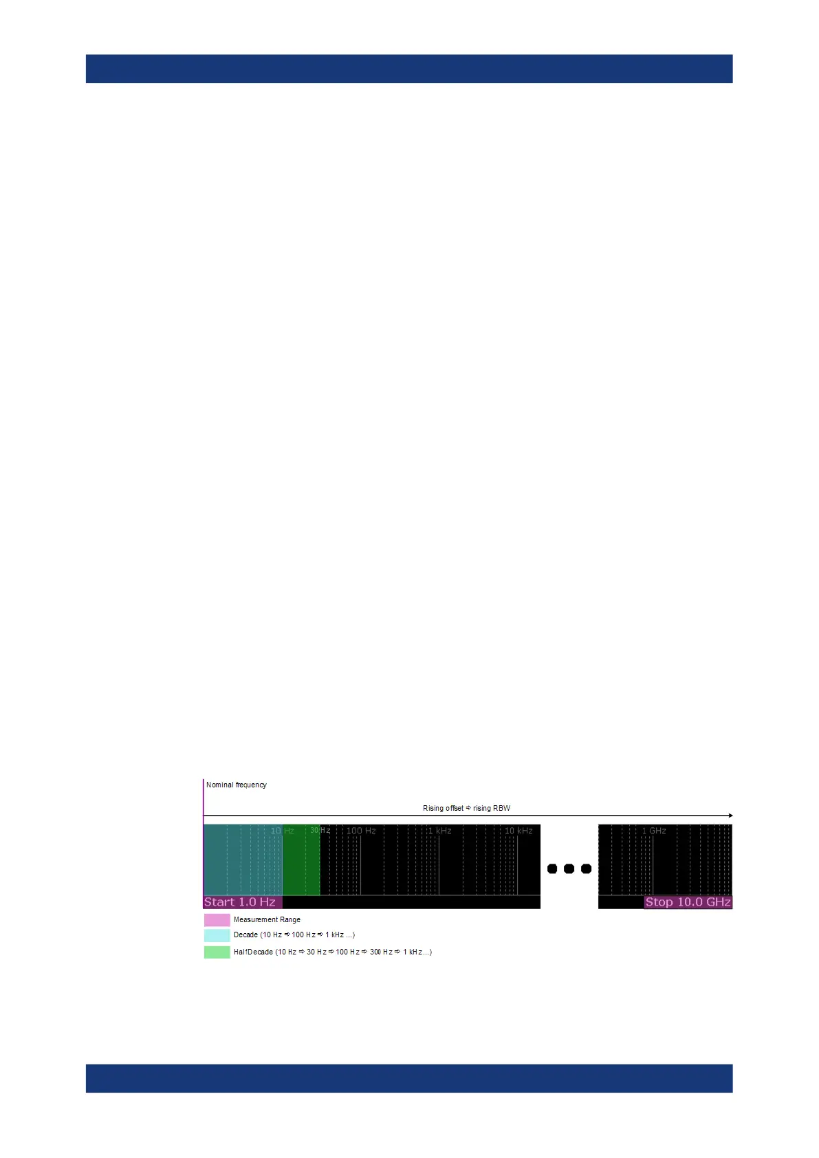
6.5.2 Measurement Range
Noise measurements determine the noise characteristics of a DUT over a particular
measurement range. This measurement range is defined by two offset frequencies.
The frequency offsets themselves are relative to the nominal frequency of the DUT.
The measurement range again is divided into several (logarithmic) decades, or, for
configuration purposes, into half decades.
Figure 6-3: Measurement range and half decades
Noise Measurement Configuration