Getting Started
R&S
®
FSPN
29User Manual 1179.4363.02 ─ 01
3.2 Instrument Tour
On the instrument tour, you can learn about the different control elements and connec-
tors on the front and back panel of the R&S FSPN.
● Front Panel View.....................................................................................................29
● Rear Panel View..................................................................................................... 37
3.2.1 Front Panel View
This chapter describes the front panel, including all function keys and connectors.
1
2 3 4 5 6 7 9 108
12
11
13
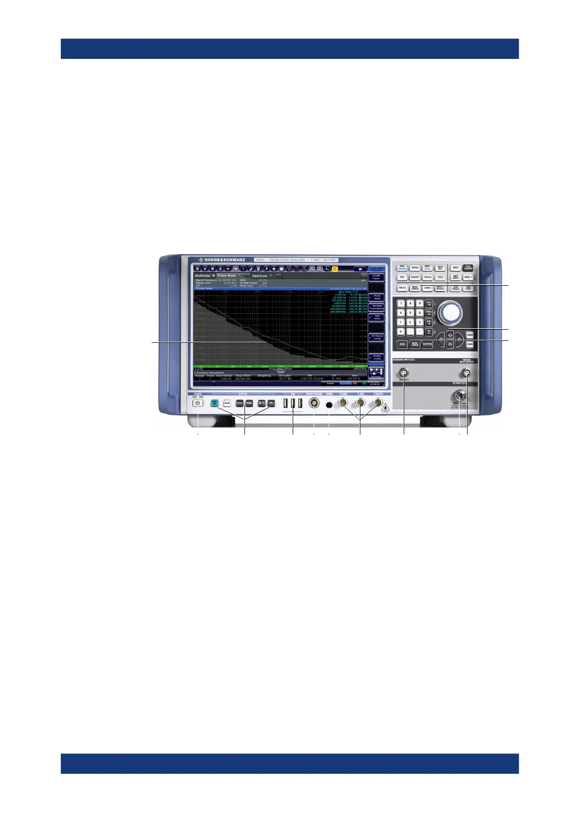
Figure 3-1: Front panel of the R&S
FSPN
1 = Display (touchscreen)
2 = Power key
3 = System control keys
4 = USB 2.0 interfaces
5 = Power sensor connector
6 = Probe power connector
7 = DC power connectors
8 = Baseband connector
9 = RF input
10 = Trigger in- and output
11 = Keypad
12 = Navigation control
13 = Function keys
● Display (Touchscreen).............................................................................................30
● Power Key...............................................................................................................31
● System Control Keys...............................................................................................31
● The Function Keys.................................................................................................. 32
● The Keypad.............................................................................................................33
● Navigation Control...................................................................................................34
● RF Input 50 Ohm.....................................................................................................35
● USB Ports............................................................................................................... 35
Instrument Tour