Getting Started
R&S
®
FSPN
37User Manual 1179.4363.02 ─ 01
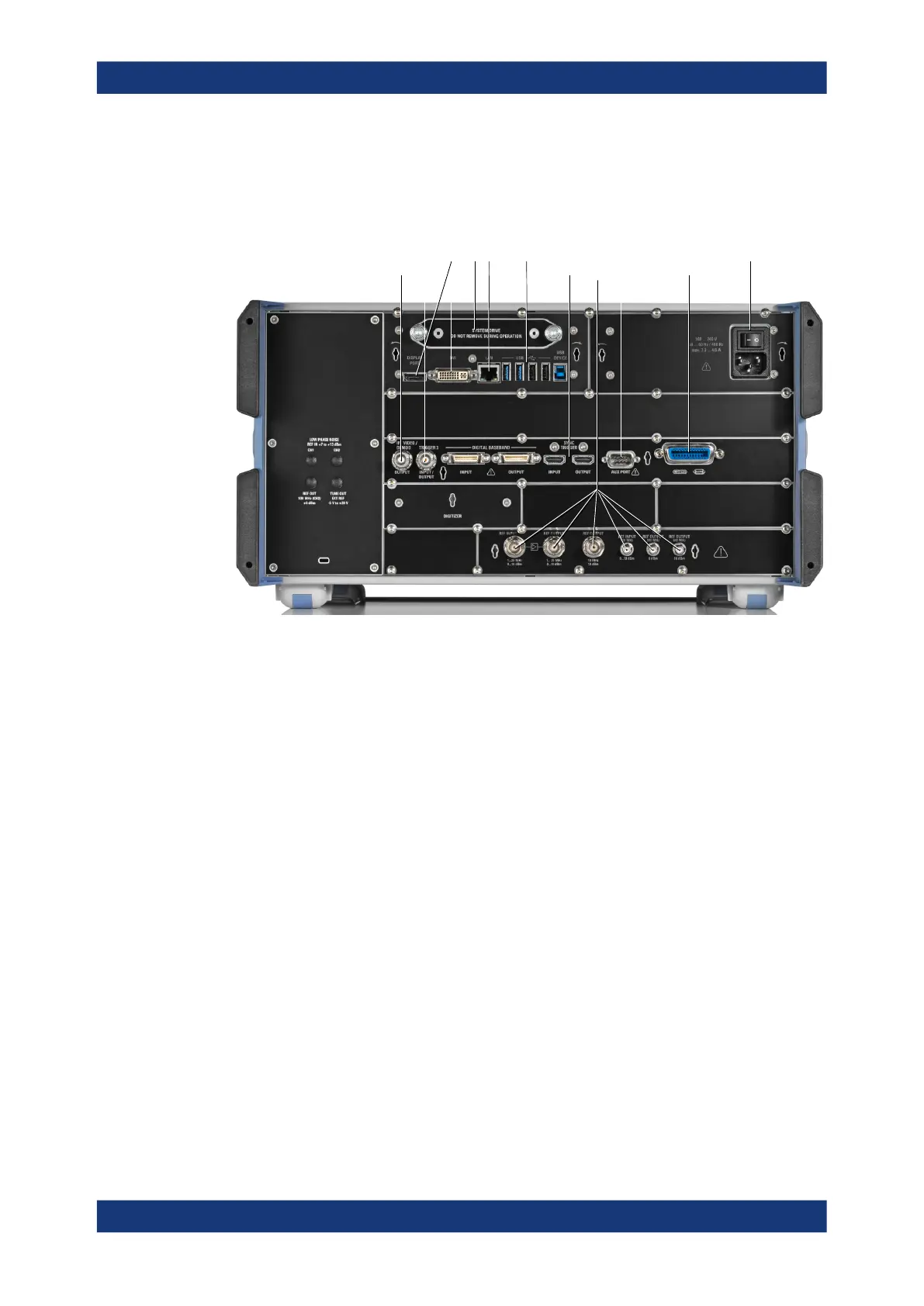
3.2.2 Rear Panel View
This figure shows the rear panel view of the R&S FSPN. The individual elements are
described in more detail in the subsequent sections.
1 23 4 5
8 9 10
11
6 7
Figure 3-2: Rear panel of the R&S
FSPN
1 = Removable hard disk
2 = AC power connector and power switch
3 = DisplayPort and DVI
4 = LAN interface
5 = USB ports
6 = IF / Video / Demod output
7 = Trigger in- / output
8 = Sync trigger input and output
9 = AUX port
10 = GPIB interface
11 = Ref input and output
For information about the trigger in- and output available on the rear panel, see Chap-
ter 3.2.1.12, "Trigger Input and Output", on page 36.
The digital baseband in- and outputs shown in the image above are not supported by
the R&S FSPN.
● Removable Hard Disk............................................................................................. 38
● AC Power Supply Connection and Main Power Switch.......................................... 38
● Display Port and DVI...............................................................................................38
● LAN......................................................................................................................... 38
● USB Ports............................................................................................................... 38
● Sync Trigger Input and Output................................................................................ 39
● Aux. Port................................................................................................................. 39
● GPIB Interface.........................................................................................................39
● OCXO......................................................................................................................39
Instrument Tour