Common Measurement Settings
R&S
®
FSPN
137User Manual 1179.4363.02 ─ 01
Defining the video bandwidth
The video filter is a lowpass filter that removes the higher frequency parts of the volt-
age from the signal (for example harmonics). This process makes the trace smoother
and makes it easier to read out results.
You can set the bandwidth of this filter, the video bandwidth or VBW, automatically or
manually ("VBW Mode").
In automatic VBW mode, the R&S FSPN automatically selects an appropriate video
bandwidth for the signal you measure.
In manual VBW mode, you can define the video bandwidth you like in the "VBW" field.
Remote command:
Mode: [SENSe:]BWIDth:VIDeo:AUTO on page 390
VBW: [SENSe:]BWIDth:VIDeo on page 390
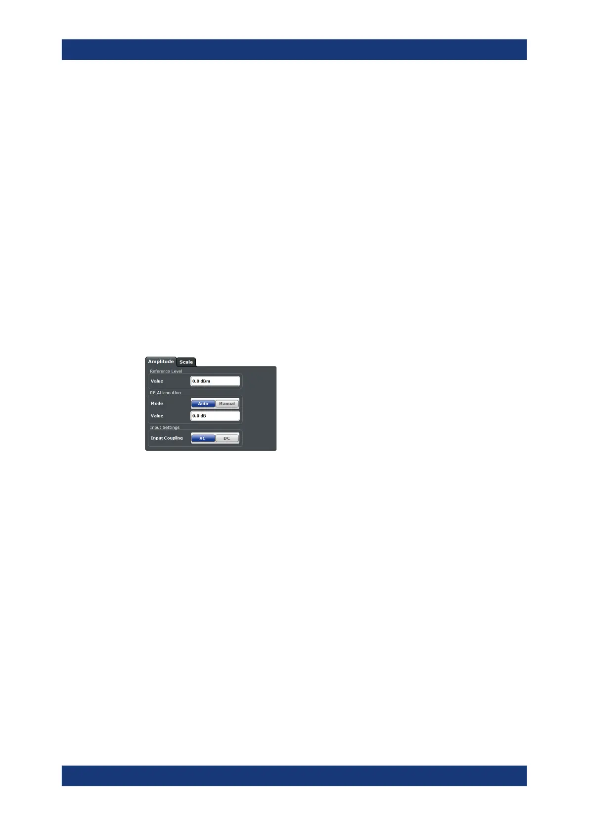
6.9.4 Amplitude Configuration
Access: "Overview" > "Amplitude / Scaling" > "Amplitude"
The amplitude settings configure the characteristics of the input signal.
The remote commands required to configure the amplitude are described in Chap-
ter 11.6.9.2, "Amplitude Configuration", on page 389.
Functions in the "Amplitude" dialog box described elsewhere:
●
RF attenuation: "Attenuating the signal" on page 103
●
Input coupling: " Input Coupling " on page 100
Defining a reference level........................................................................................... 137
Defining a reference level
The reference level is the expected level of the signal you are measuring.
Because the hardware of the R&S FSPN is adapted according to this value, it is rec-
ommended that you set the reference level close above the expected maximum signal
level.
The reference level is a value between 0 dB, and 30 dBm and is always coupled to the
attenuation. When you turn on auto attenuation, the R&S FSPN selects an attenuation
that results in a nominal signal level of (about) 0 dBm to protect the input mixer.
Remote command:
INPut<1|2>:RLEVel on page 389
PN Transient Analysis Configuration