Section 4 Clock Pulse Generators
Rev. 7.00 Mar 10, 2005 page 108 of 652
REJ09B0042-0700
Table 4.2 Crystal Oscillator Parameters
Frequency (MHz) 4 4.193
RS max (Ω) 100 100
C
0
max (pF) 16 16
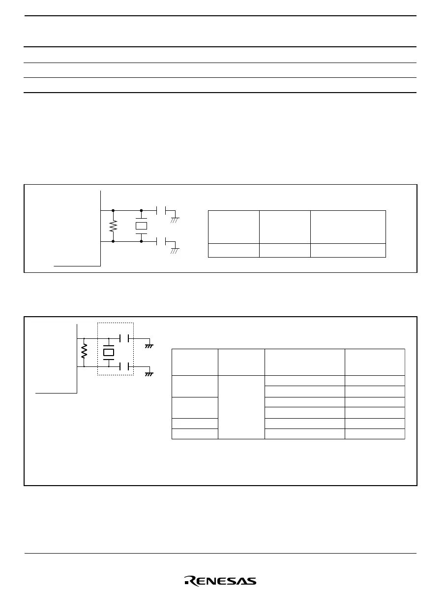
Connecting a Ceramic Oscillator
Figure 4.5(1) shows a typical method of connecting a ceramic oscillator to the H8/38024 or
H8/38024R Group, and figure 4.5(2) shows a typical method of connecting a crystal oscillator to
the H8/38024S and H8/38124 Group.
1
2
C
1
C
2
OSC
OSC
R
f
R = 1 M ±20%
f
Ω
Frequency
Ceramic
oscillator
4.0 MHz Murata 30 pF ±10%
C
1
, C
2
Recommendation
value
Figure 4.5(1) Typical Connection to Ceramic Oscillator
(H8/38024, H8/38024R Group)
Frequency
2.0 MHz
10.0 MHz
16.0 MHz
*
1
20.0 MHz
*
2
Murata
Ceramic
oscillator
Products name
Ceramic oscillator
R
f
= 1 MΩ ±20%
OSC
1
OSC
2
R
f
C
1
C
2
CSTCC2M00G53-B0
CSTCC2M00G56-B0
CSTLS10M0G53-B0
CSTLS10M0G56-B0
CSTLS16M0X53-B0
CSTLS20M0X53-B0
15 pF ±20%
47 pF ±20%
15 pF ±20%
47 pF ±20%
15 pF ±20%
15 pF ±20%
C
1
, C
2
Recommendation
value
Notes: Circuit constants should be determined in consultation
with the resonator manufacturer.
1. This does not apply to the H8/38024S Group.
2. H8/38124 Group only
Figure 4.5(2) Typical Connection to Ceramic Oscillator
(H8/38024S, H8/38124 Group)

 Loading...


