Section 4 Clock Pulse Generators
Rev. 7.00 Mar 10, 2005 page 109 of 652
REJ09B0042-0700
Notes on Board Design
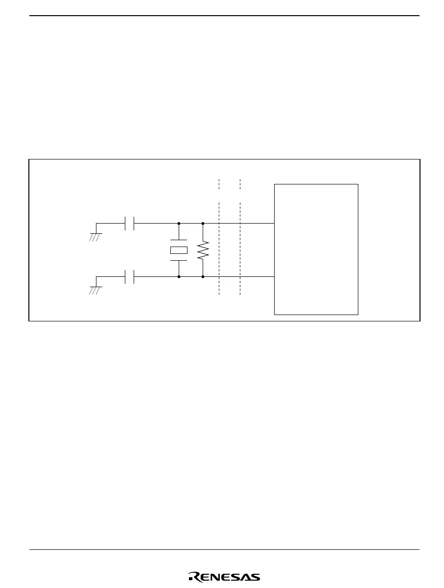
When generating clock pulses by connecting a crystal or ceramic oscillator, pay careful attention
to the following points.
Avoid running signal lines close to the oscillator circuit, since the oscillator may be adversely
affected by induction currents. (See figure 4.6.)
The board should be designed so that the oscillator and load capacitors are located as close as
possible to pins OSC
1
and OSC
2
.
OSC
OSC
C
1
C
2
Signal A Signal B
2
1
To be avoided
××
Figure 4.6 Board Design of Oscillator Circuit
Note: The circuit parameters above are recommended by the crystal or ceramic oscillator
manufacturer.
The circuit parameters are affected by the crystal or ceramic oscillator and floating
capacitance when designing the board. When using the oscillator, consult with the crystal
or ceramic oscillator manufacturer to determine the circuit parameters.

 Loading...


