Section 6 ROM
Rev. 7.00 Mar 10, 2005 page 150 of 652
REJ09B0042-0700
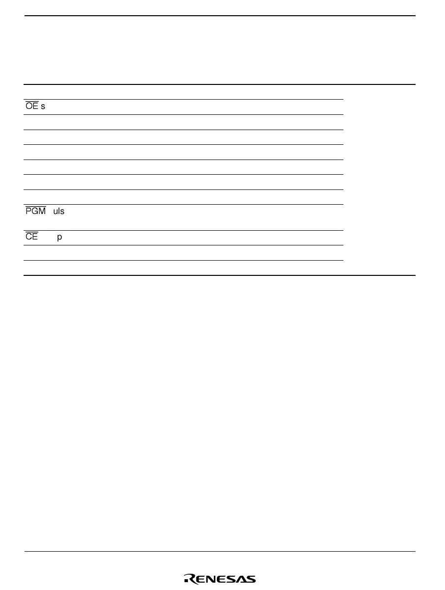
Table 6.4 AC Characteristics
Conditions: V
CC
= 6.0 V ±0.25 V, V
PP
= 12.5 V ±0.3 V, T
a
= 25°C ±5°C
Item Symbol Min Typ Max Unit Test Condition
Address setup time t
AS
2 — — µs Figure 6.5
*
1
OE
setup time t
OES
2 ——µs
Data setup time t
DS
2 ——µs
Address hold time t
AH
0 ——µs
Data hold time t
DH
2 ——µs
Data output disable time t
DF
*
2
— — 130 ns
V
PP
setup time t
VPS
2 ——µs
Programming pulse width t
PW
0.19 0.20 0.21 ms
PGM
pulse width for overwrite
programming
t
OPW
*
3
0.19 — 5.25 ms
CE
setup time t
CES
2 ——µs
V
CC
setup time t
VCS
2 ——µs
Data output delay time t
OE
0 — 200 ns
Notes: 1. Input pulse level: 0.45 V to 2.4 V
Input rise time/fall time ≤ 20 ns
Timing reference levels Input: 0.8 V, 2.0 V
Output: 0.8 V, 2.0 V
2. t
DF
is defined at the point at which the output is floating and the output level cannot be
read.
3. t
OPW
is defined by the value given in figure 6.4, High-Speed, High-Reliability
Programming Flow Chart.

 Loading...


