Section 10 Serial Communication Interface
Rev. 7.00 Mar 10, 2005 page 352 of 652
REJ09B0042-0700
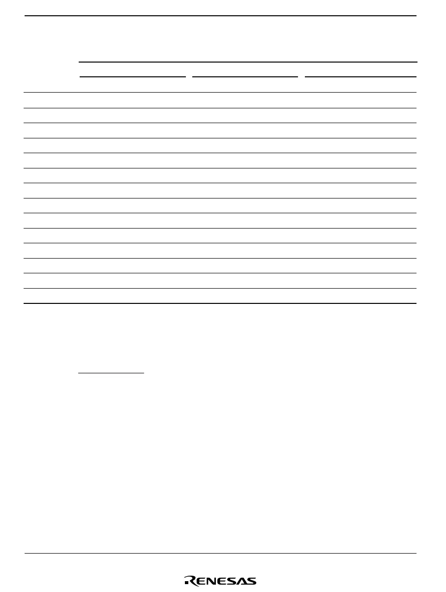
Table 10.6 Examples of BRR Settings for Various Bit Rates (Synchronous Mode) (2)
φ
φφ
φ
5 MHz 8 MHz 10 MHz
Bit Rate
(bit/s) n N Error n N Error n N Error
200 ——————0 12499 0
250 ———3 1240 2 6240
300 ——————0 8332 0
500 ———2 2490 0 4999 0
1K ———2 1240 0 2499 0
2.5K ———2 490 0 9990
5K 0 249 0 2 24 0 0 499 0
10K 0 124 0 0 199 0 0 249 0
25K 049007900990
50K 024003900490
100K ———0 190 0 240
250K 040070090
500K ———030040
1M ———0 1 0 ———
Blank: Cannot be set.
— : A setting can be made, but an error will result.
Notes: The value set in BRR is given by the following equation:
φ
N =
(4 • 2
2n
• B)
– 1
where B: Bit rate (bit/s)
N: Baud rate generator BRR setting (0 ≤ N ≤ 255)
φ: System clock frequency
n: Baud rate generator input clock number (n = 0, 2, or 3)
(The relation between n and the clock is shown in table 10.7.)
 Loading...


