Section 10 Serial Communication Interface
Rev. 7.00 Mar 10, 2005 page 387 of 652
REJ09B0042-0700
7. Relation between RDR reads and bit RDRF
In a receive operation, SCI3 continually checks the RDRF flag. If bit RDRF is cleared to 0 when
reception of one frame ends, normal data reception is completed. If bit RDRF is set to 1, this
indicates that an overrun error has occurred.
When the contents of RDR are read, bit RDRF is cleared to 0 automatically. Therefore, if bit
RDR is read more than once, the second and subsequent read operations will be performed while
bit RDRF is cleared to 0. Note that, when an RDR read is performed while bit RDRF is cleared to
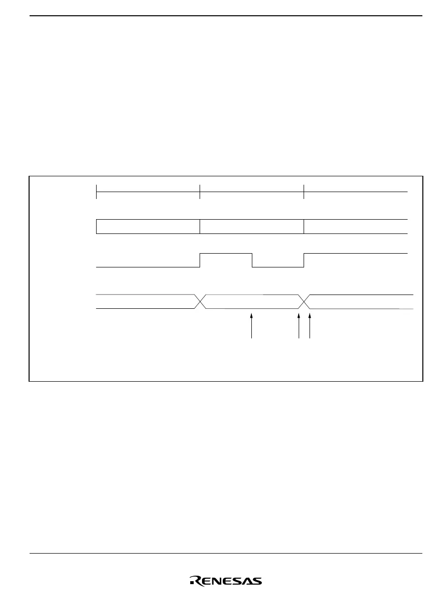
0, if the read operation coincides with completion of reception of a frame, the next frame of data
may be read. This is illustrated in figure 10.22.
Communication
line
RDRF
RDR
Frame 1 Frame 2 Frame 3
Data 1
Data 1
RDR read RDR read
Data 1 is read at point
(A)
Data 2 Data 3
Data 2
(A)
Data 2 is read at point
(B)
(B)
Figure 10.22 Relation between RDR Read Timing and Data
In this case, only a single RDR read operation (not two or more) should be performed after first
checking that bit RDRF is set to 1. If two or more reads are performed, the data read the first time
should be transferred to RAM, etc., and the RAM contents used. Also, ensure that there is
sufficient margin in an RDR read operation before reception of the next frame is completed. To
be precise in terms of timing, the RDR read should be completed before bit 7 is transferred in
synchronous mode, or before the STOP bit is transferred in asynchronous mode.

 Loading...


