Section 1 Overview
Rev. 7.00 Mar 10, 2005 page 20 of 652
REJ09B0042-0700
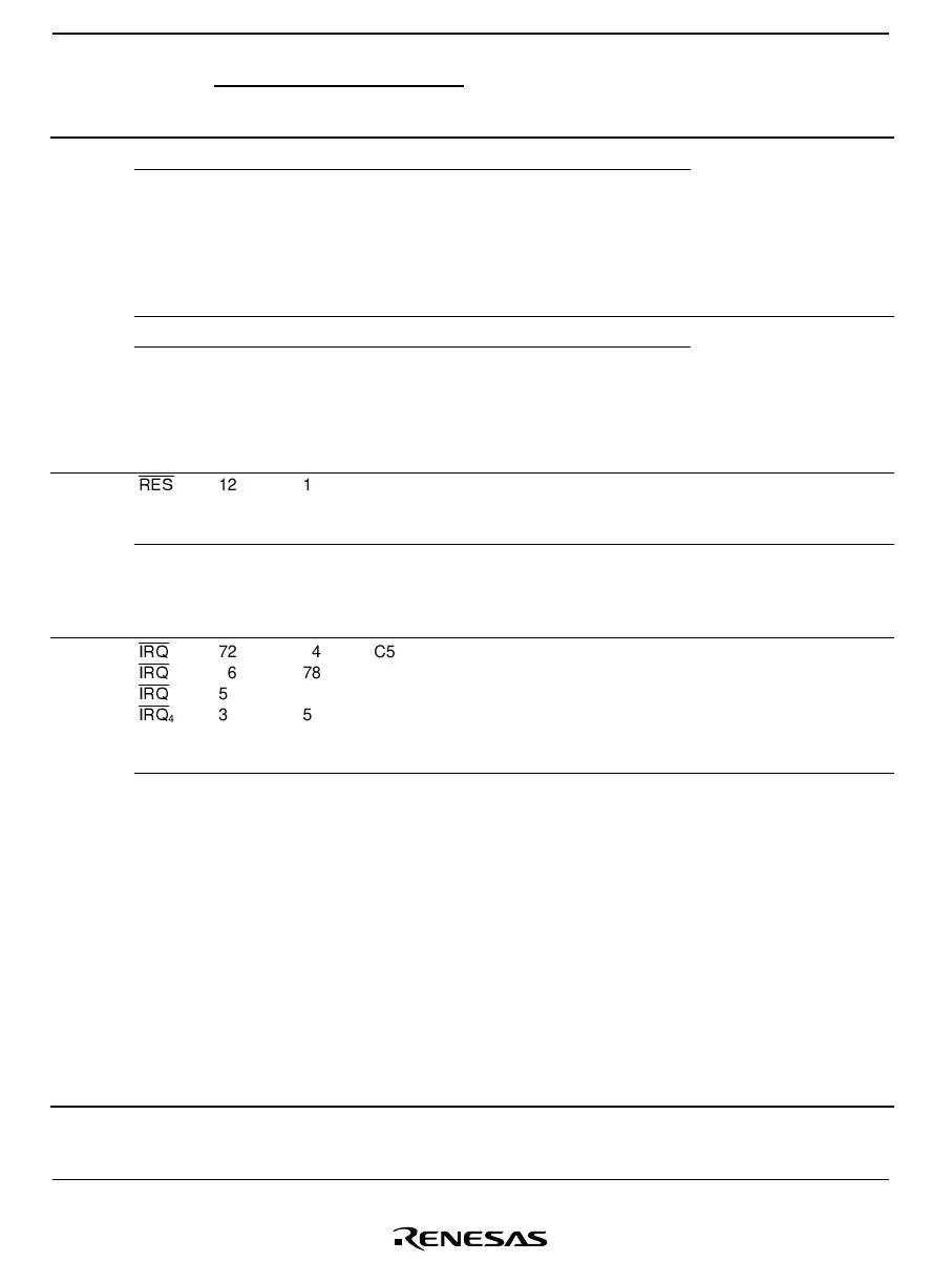
Pin No.
Type Symbol
FP-80A
TFP-80C
FP-80B TLP-85V
Pad
No.
*
1
Pad
No.
*
2
Pad
No.
*
3
I/O Name and Functions
OSC
1
10 12 F2 11 12 10 Input
Clock
pins
OSC
2
9 11 E3 10 11 9 Output
These pins connect to a
crystal or ceramic
oscillator, or can be used
to input an external clock.
See section 4, Clock
Pulse Generators, for a
typical connection
diagram.
X
1
6 8 D3 676Input
X
2
7 9 D2 787Output
These pins connect to a
32.768-kHz or 38.4-kHz
*
5
crystal oscillator.
See section 4, Clock
Pulse Generators, for a
typical connection
diagram.
System
control
RES
12 14 F3 13 14 12 Input
Reset: When this pin is
driven low, the chip is
reset
TEST 11 13 E2 12 13 11 Input Test pin: This pin is
reserved and cannot be
used. It should be
connected to V
SS
.
Interrupt
pins
IRQ
0
IRQ
1
IRQ
3
IRQ
4
72
76
5
3
74
78
7
5
C5
B3
D1
B2
73
77
5
3
74
78
6
4
72
76
5
3
Input IRQ interrupt request 0,
1, 3, and 4: These are
input pins for edge-
sensitive external
interrupts, with a selection
of rising or falling edge
IRQAEC 60 62 C10 61 62 60 Input
Asynchronous event
counter event signal:
This is an interrupt input
pin for enabling
asynchronous event
input.
On the H8/38124 Group,
this must be fixed at V
CC
or GND because the
oscillator is selected by
the input level during
resets. Refer to section 4,
Clock Pulse Generators,
for information on the
selection method.

 Loading...


