ECODRIVE03 Drive Controllers ECODRIVE03 Auxiliary Bleeder Module BZM01.3 6-7
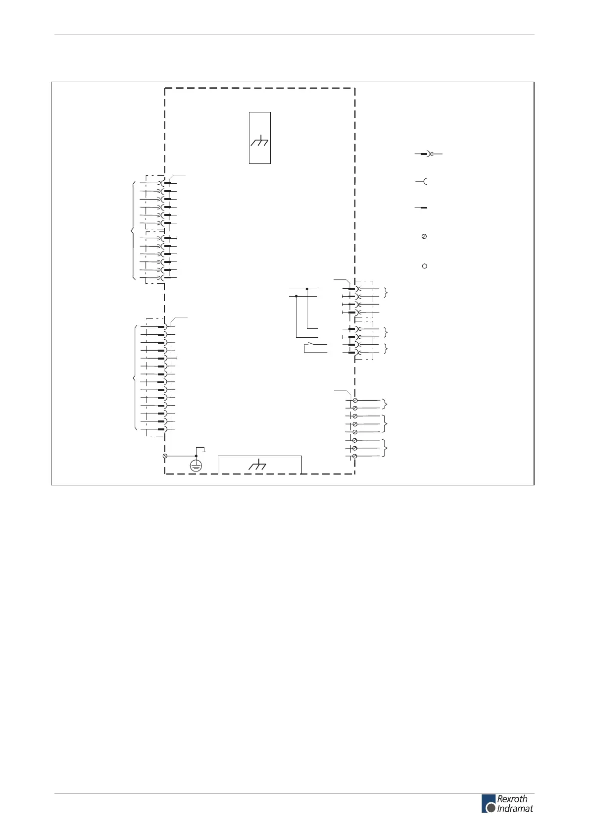
Complete Terminal Diagram
Auxiliary Bleeder Module BZM01.3
X5
L+
L-
A1
A2
A3
DC bus connection
AP5308f1.FH7
XS1
XE1
mains connection
L1
L2
L3
protective conductor connection
(power line) >= 10 mm ²
Interface for
ZKS control
digital and analog
inputs and outputs
XS2
for internal use only
8
X1
ready for operation
2
5
7
+24V
+24V
connection for
control voltage
1
0V
0V
3
0V
0V
0V
4
0V
6
Bb
Bb
connection for control voltage
to additional devices
X2
1
2
3
4
5
6
7
8
10
11
12
ZKS1
0V
ZKS2
9
+24Vpro
Load
Ready
ClearError
Warning
X3
1
2
3
4
5
6
8
9
10
11
7
12
13
14
RxD
TxD
0V
XS*: Shield connection
XE*: Protective conductor
connection
X* : Clamp pin
designation
Spring tension
terminal socket
Plug connection
socket
Plug connection
pin
Screw
connections
Electric conduction
to the device
housing
n.c.
Fig. 6-9: Terminal diagram - BZM01.3
customerservice@hyperdynesystems.com | (479) 422-0390

 Loading...