7-6 ECODRIVE03 Auxiliary Capacitance Module CZM01.3 ECODRIVE03 Drive Controllers
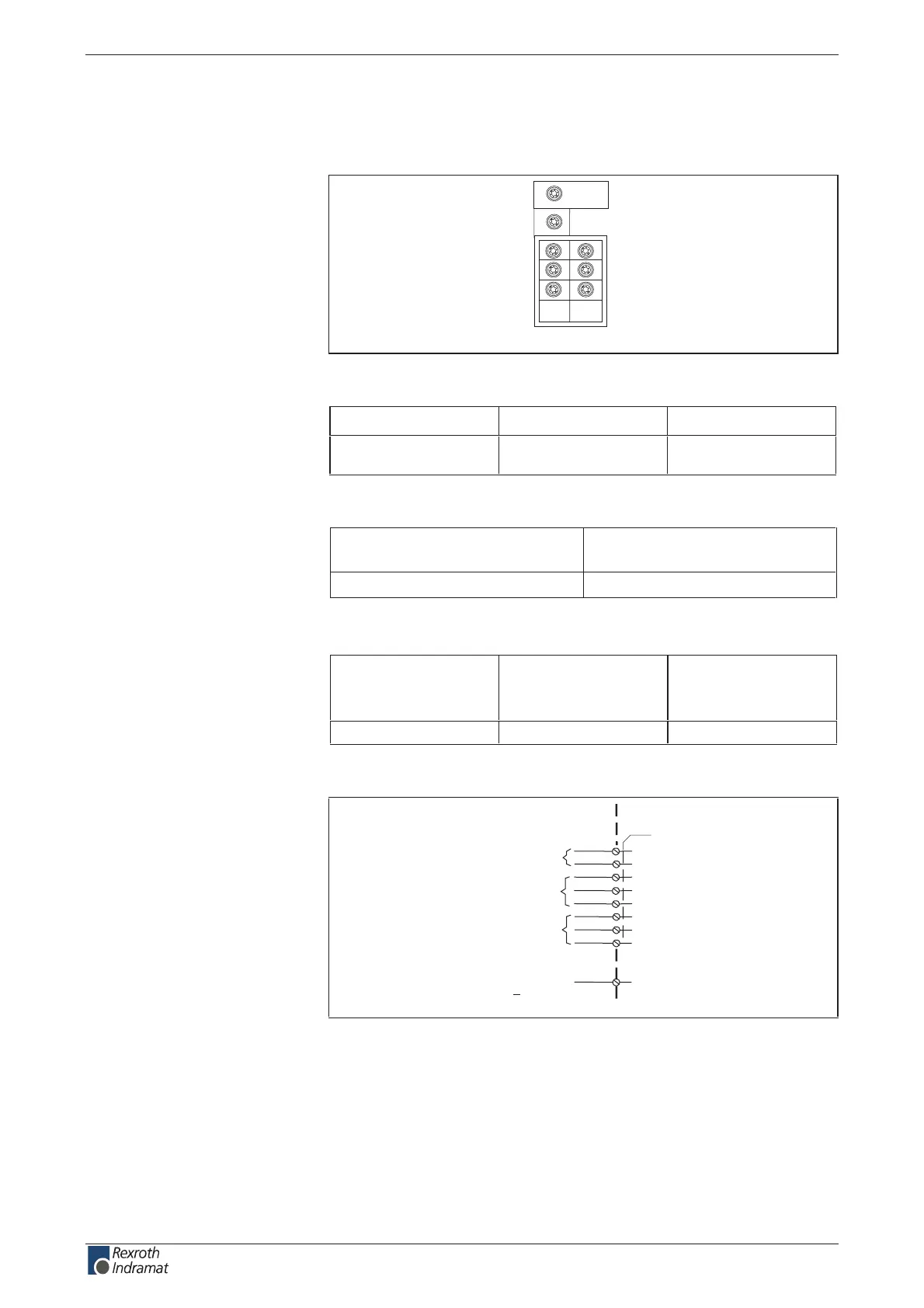
X5, DC bus connection
Technical description of connector
Ap5267f1.FH7
L+
L-
L1
L2
L3
A1
A2
A3
Fig. 7-8: Connector X5
Type No. of pins Design
Terminal block 2 / 3 / 3 Screw for ring
terminals M5
Fig. 7-9: Design
min. tightening torque
[Nm]
max. tightening torque
[Nm]
0.35.2
Fig. 7-10: Tightening torque
Cross section
single wire
[mm ²]
Cross section
multi core wire
[mm ²]
Cross section
in AWG
gauge no.:
--52--
Fig. 7-11: Connection cross section
device-external device-internal
AP5317F1.FH7
X5
n.c.
L1
L2
L+
L-
DC bus connection
L3
XE1
Ground wire
connection
> 10mm ²
A1
A2
A3
n.c.
Fig. 7-12: DC bus connection of auxiliary capacitance module CZM01.3 – X5
Illustration:
Design:
Tightening torque:
Connection cross section:
Connection:
customerservice@hyperdynesystems.com | (479) 422-0390

 Loading...