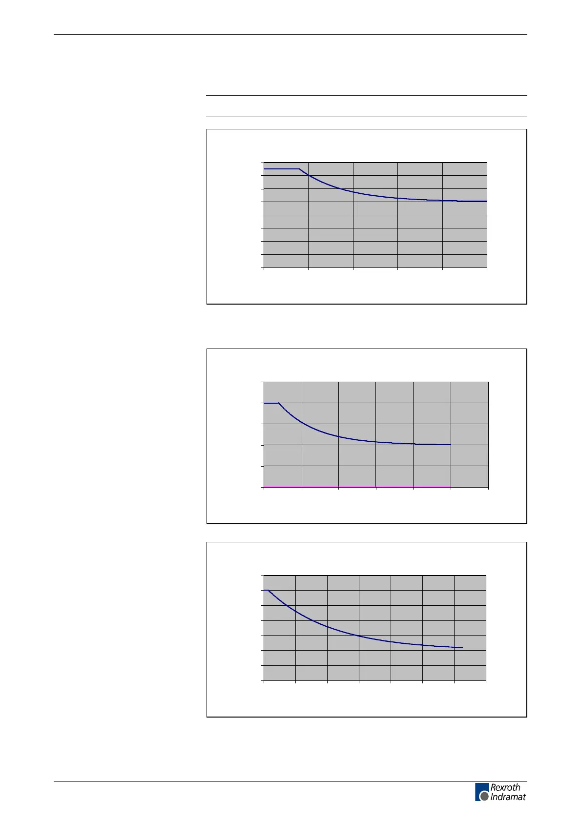
ECODRIVE03 Drive Controllers ECODRIVE03 DKC**.040, DKC**.100, DKC**.200 4-27
Allowed DC bus Peak Power
Note: Diagrams apply to single and central supply!
Relationship peak to DC bus
continuous power
0
0,2
0,4
0,6
0,8
1
1,2
1,4
1,6
0 0,5 1 1,522,5
t in s
P
ZWS
/P
ZWD
Fig. 4-27: Allowed peak power in DC bus of DKC**.3-040-7-FW
DKC**.3-040-7-FWs are not suited for drive applications if the required
intermittent operating power of the unit ’s nominal power exceeds 50%!
Relationship peak to DC bus
continuous power
0
0,5
1
1,5
2
2,5
0 5 10 15 20 25 30
t in s
P
ZWS
/P
ZWD
Fig. 4-28: Allowed peak power in DC bus of DKC**.3-100-7-FW
Relationship peak to DC bus
continuous power
0
0,5
1
1,5
2
2,5
3
3,5
0 20 40 60 80 100 120 140
t in s
P
ZWS
/P
ZWD
Fig. 4-29: Allowed peak power in DC bus of DKC**.3-200-7-FW
DKC**.3-040-7-FW
DKC**.3-100-7-FW
DKC**.3-200-7-FW
customerservice@hyperdynesystems.com | (479) 422-0390

 Loading...