5-32 srellortnoC evirD 30EVIRDOCE610-3.**CKD 30EVIRDOCE
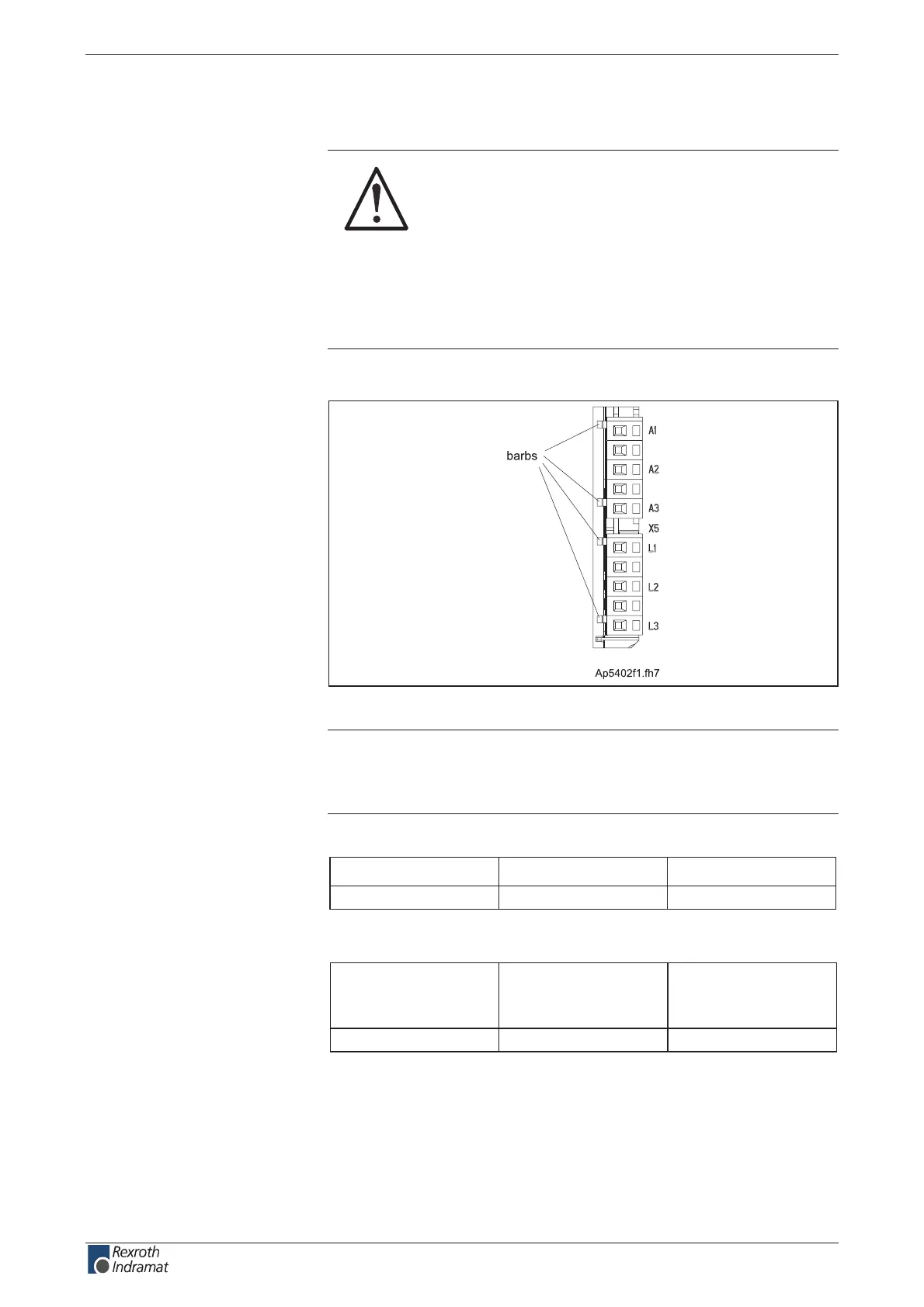
X5, Motor and Mains Connections
DANGER
Lethal electric shock caused by live parts with
more than 50 V!
Before working on the drive controller, switch o the
power supply via the main switch or the fuse.
Always mount or dismount both connectors (motor
connector and mains connector) on the drive
controller at the same time.
Observe the information contained in chapter 3
Safety Instructions for Electric Drives and Controls".
Technical description of connector
Fig. 5-52: Connector X5
Note:
• To pull o the connectors, loosen the barbs.
• The maximum number of insertion/withdrawal cycles is limited to 15.
Type No. of pins Design
connection block 2 x 3 bushing on connector
Fig. 5-53: Design
Cross section
single wire
[mm ²]
max. connectable
cross section
[mm ²]
max. Cross section
in AWG
gauge no.:
615,15,1
Fig. 5-54: Connection cross section
Illustration:
Design:
Connection cross section:
customerservice@hyperdynesystems.com | (479) 422-0390

 Loading...