12-6 srellortnoC evirD 30EVIRDOCEtenibaC lortnoC eht gnitcurtsnoC
Mounting Position and Distances
Mounting Position
The mounting of the drive controller device DKC, the auxiliary braking
resistor module BZM and the auxiliary capacitance module CZM is to
be performed in such a way that their longitudinal axis correlates with
the natural direction of convection (connection block X5 towards the
bottom). The natural convection supports the forced cooling air
stream. The build up of warm spots in the device is inhibited.
Put the backs of the drive controllers on the mounting surface
(mounting plate)of the control cabinet with all-over contact.
Distances
The power dissipation of the drive controller DKC and the auxiliary
braking
resistor module BZM means that the cooling air from the point of
entrance on the underside of the unit until the point of exit on the top side
is warmed up. The following illustrates this increase as dependent on the
occurring continuous braking resistor power.
The appropriate distance "d" is specied in the curve (interpolation
allowed).
MB5013F1.FH7
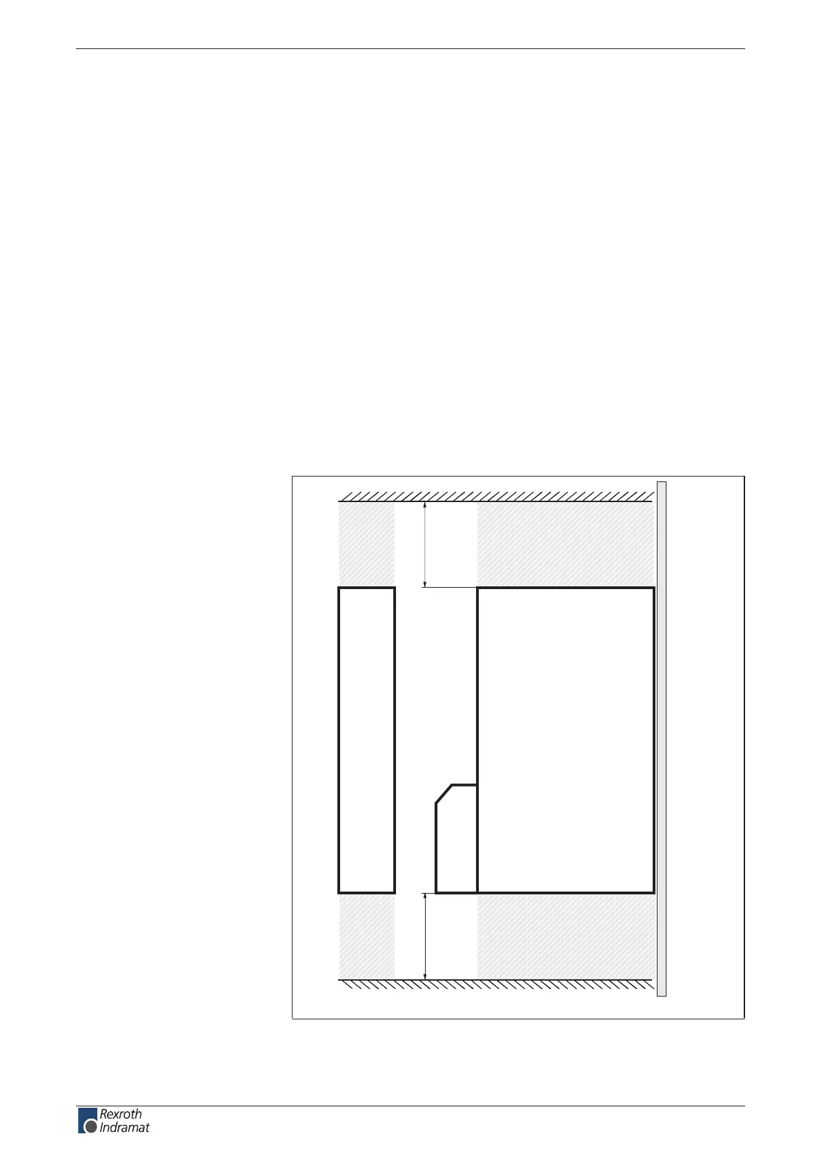
control cabinet mounting plate
cooling air outlet
cooling air outlet
cooling air inlet
cooling air inlet
d
c
Fig. 12-10: Exit and entrance of cooling air
Temperature Increase of
Cooling Air
customerservice@hyperdynesystems.com | (479) 422-0390

 Loading...