5-18 srellortnoC evirD 30EVIRDOCE610-3.**CKD 30EVIRDOCE
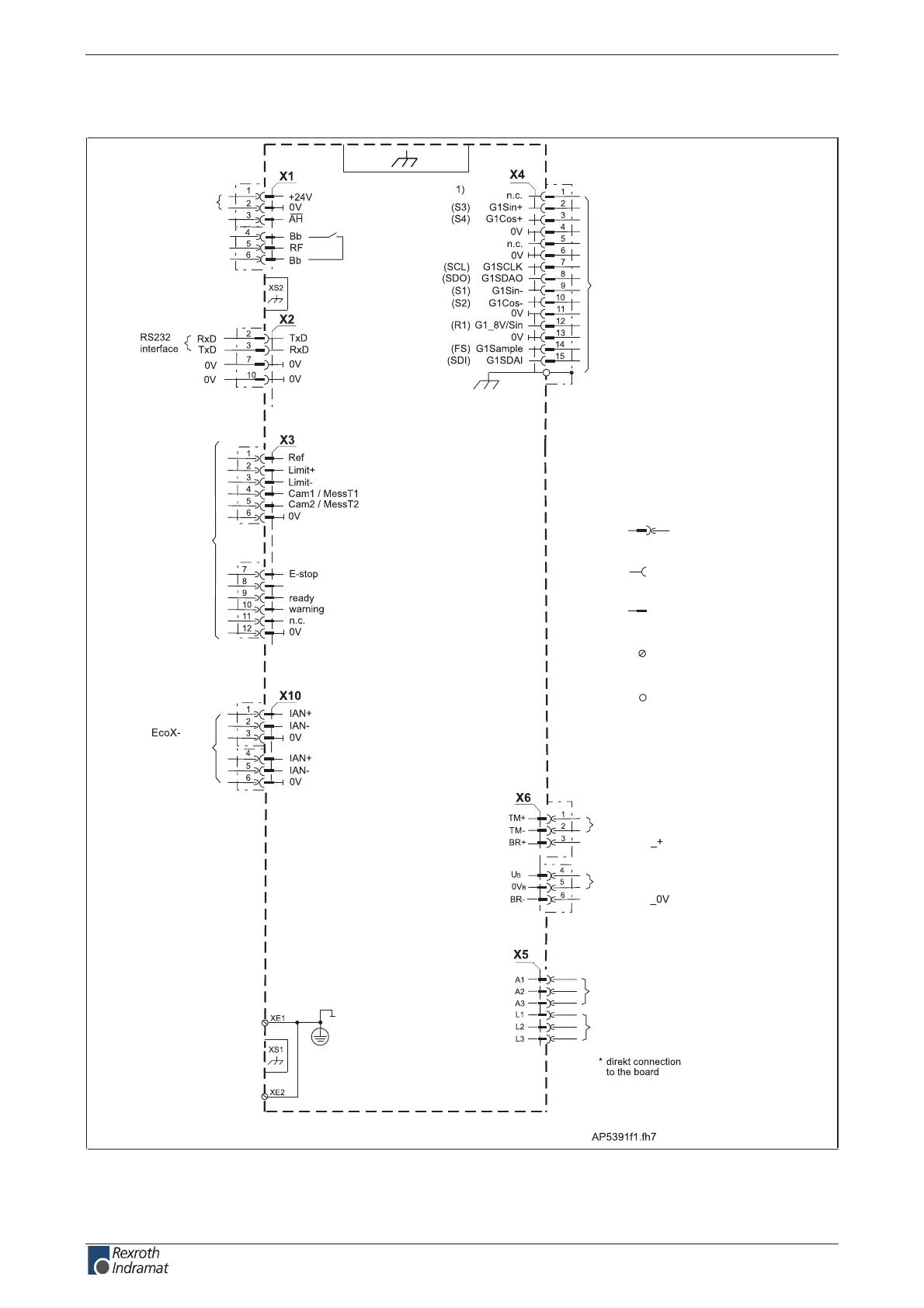
Independent of the drive controller type – total connecting diagram
motor temperature monitoring
holding brake
expansion
interface
holding brake
XS3
encoder 1
connection for
control voltage
drive halt
drive enable
ready for operation
ready for operation
digital inputs
and outputs
clear error
protective coductor
connection (motor)
protective coductor
connection (mains)
>= 10 mm ²
voltage connection for brake
motor connection*
mains connection*
DKC**.3-016 drive controller
XS: shield connection
XE: protective conductor
connection
X: clamp pin
designation
spring tension
terminal socket
plug connection
socket
plug connection
pin
screw
connections
electric conduction
to the device
housing
Fig. 5-21: Total connection diagram for DKC**.3-016
customerservice@hyperdynesystems.com | (479) 422-0390

 Loading...