610-3.**CKD 30EVIRDOCEsrellortnoC evirD 30EVIRDOCE 5-19
X1, Connections for control voltage
Technical description of connector
Ap5382f1.FH7
123
456
Fig. 5-22: Connector X1
Type No. of pins Design
Spring contact 2 x 3 Bushing on connector
Fig. 5-23: Design
Cross section
single wire
[mm ²]
Cross section
multi core wire
[mm ²]
Cross section
in AWG
Gauge no.:
0,2-2,5 1,5-2,5 16-12
Fig. 5-24: Connection cross section
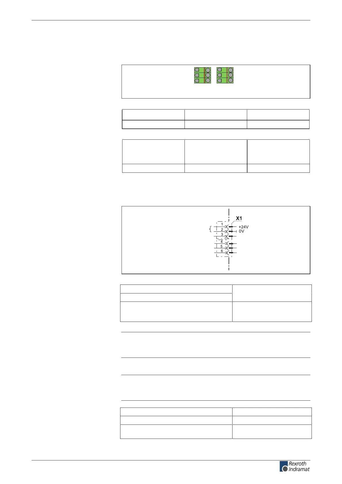
24V control voltage supply (+24V and 0V)
AP5392F1.FH7
device-external device-internal
connection for control voltage
Fig. 5-25: Connections for control voltage
Voltage at X1/1 against X1/2:
Current or power consumption X1/1:
see page 5-6 "Control voltage
connection"
egnar egatlov dewolla aiV:noitcetorp egatlov esreveR
using internal protection
diodes
Note: Strong mechanical inuence on the test tap of the terminals
can increase the transition resistance and destroy the
terminals.
Note: The input 0 V is connected directly to the device potential. The
utilization of an insulation monitoring for +24 V and 0 V against
device is therefore not possible!
mm 1 .nim:noitces ssorc eriw ²
elbissop fi lellarap:gnituor eriw
Max. allowed inductance between 24V source
and X1:
100 µH
(equals about 2 x 75 m)
Illustration:
Design:
Connection cross section:
Connection
+24V and 0V:
Connection loads
+24V and 0V:
wire
+24V and 0V:
customerservice@hyperdynesystems.com | (479) 422-0390

 Loading...